System reset
ST10F276E
19.5
Watchdog timer reset
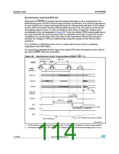
When the watchdog timer is not disabled during the initialization, or serviced regularly
during program execution, it will overflow and trigger the reset sequence.
Unlike hardware and software resets, the watchdog reset completes a running external bus
cycle if this bus cycle either does not use READY, or if READY is sampled active (low) after
the programmed wait states.
When READY is sampled inactive (high) after the programmed wait states the running
external bus cycle is aborted. Then the internal reset sequence is started.
Bit P0.12...P0.8 are latched at the end of the reset sequence and bit P0.7...P0.2 are cleared
(that is written at ‘1’).
A Watchdog reset is always taken as synchronous: there is no influence on Watchdog Reset
behavior with RPD status. In case Bidirectional Reset is selected, a Watchdog Reset event
pulls RSTIN pin low: this occurs only if RPD is high; if RPD is low, RSTIN pin is not pulled
low even though Bidirectional Reset is selected.
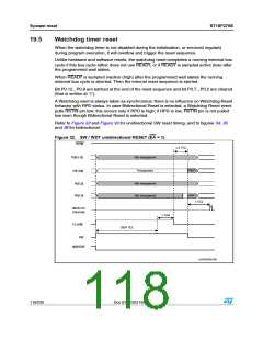
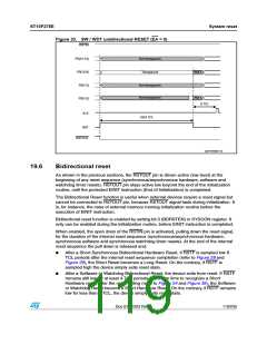
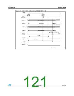
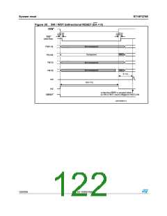
Refer to Figure 32 and Figure 33 for unidirectional SW reset timing, and to figures 34, 35
and 36 for bidirectional.
Figure 32. SW / WDT unidirectional RESET (EA = 1)
234.)
dꢀꢁ 4#,
0ꢉ;ꢀꢃꢐꢀꢈ=
0ꢉ;ꢀꢁꢐꢆ=
.OT TRANSPARENT
4RANSPARENT
.OT Tꢌ
.OT Tꢌ
.OT TRANSPARENT
.OT TRANSPARENT
0ꢉ;ꢊꢐꢁ=
0ꢉ;ꢀꢐꢉ=
ꢊ 4#,
)"53ꢅ#3
ꢍINTERNALꢏ
d ꢀMS
&,!234
ꢀꢉꢁꢇ 4#,
234
234/54
'!0'2)ꢉꢉꢀꢉꢋ
118/235
Doc ID 12303 Rev 3

 STMICROELECTRONICS [ ST ]