ST10F276E
System reset
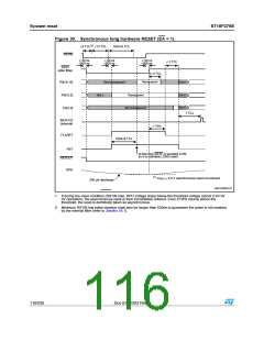
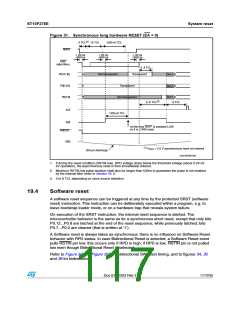
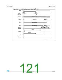
Figure 31. Synchronous long hardware RESET (EA = 0)
ꢍꢁꢏ
ꢇ 4#,
ꢀꢁ 4#,
ꢀꢉꢁꢇꢑꢆ 4#,
234).
t ꢃꢉ NS
dꢃꢉꢉ NS
t ꢃꢉ NS
t ꢃꢉ NS
dꢃꢉꢉ NS
dꢃꢉꢉ NS
234&
ꢍAFTER FILTERꢏ
ꢈꢌꢌꢇ 4#,
4RANSPARENT
0ꢉ;ꢀꢃꢐꢀꢈ=
.OT TRANSPARENT
.OT Tꢌ
0ꢉ;ꢀꢁꢐꢁ=
0ꢉ;ꢀꢐꢉ=
4RANSPARENT
.OT Tꢌ
.OT Tꢌ
.OT TRANSPARENT
ꢍꢈꢏ
ꢈꢌꢌꢆ 4#,
ꢆ 4#,
!,%
ꢀꢉꢁꢇꢑꢆ 4#,
234
!T THIS TIME 234& IS SAMPLED ,/7
SO IT IS ,/.' RESET
234/54
20$
ꢍꢀꢏ
6
ꢔ ꢁꢌꢃ 6 ASYNCHRONOUS RESET NOT ENTERED
20$
ꢁꢉꢉ ! DISCHARGE
'!0'2)ꢉꢉꢀꢉꢆ
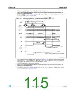
1. If during the reset condition (RSTIN low), RPD voltage drops below the threshold voltage (about 2.5V for
5V operation), the asynchronous reset is then immediately entered.
2. Minimum RSTIN low pulse duration shall also be longer than 500ns to guarantee the pulse is not masked
by the internal filter (refer to Section 19.1).
3. 3 to 8 TCL depending on clock source selection.
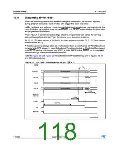
19.4
Software reset
A software reset sequence can be triggered at any time by the protected SRST (software
reset) instruction. This instruction can be deliberately executed within a program, e.g. to
leave bootstrap loader mode, or on a hardware trap that reveals system failure.
On execution of the SRST instruction, the internal reset sequence is started. The
microcontroller behavior is the same as for a synchronous short reset, except that only bits
P0.12...P0.8 are latched at the end of the reset sequence, while previously latched, bits
P0.7...P0.2 are cleared (that is written at ‘1’).
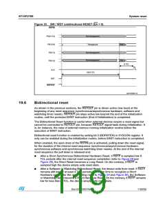
A Software reset is always taken as synchronous: there is no influence on Software Reset
behavior with RPD status. In case Bidirectional Reset is selected, a Software Reset event
pulls RSTIN pin low: this occurs only if RPD is high; if RPD is low, RSTIN pin is not pulled
low even though Bidirectional Reset is selected.
Refer to Figure 32 and Figure 33 for unidirectional SW reset timing, and to figures 34, 35
and 36 for bidirectional.
Doc ID 12303 Rev 3
117/235

 STMICROELECTRONICS [ ST ]