powerSTEP01
Phase current control: voltage mode
8.1
PWM sinewave generators
The two voltage sinewaves applied to the stepper motor phases are generated by two PWM
modulators.
The PWM frequency (fPWM) is proportional to the oscillator frequency (fOSC) and can be
obtained through the following formula:
Equation 3
f
fPWM = -----O----S----C----- ⋅ m
512 ⋅ N
'N' is the integer division factor and 'm' is the multiplication factor. 'N' and 'm' values can be
programmed by F_PWM_INT and F_PWM_DEC parameters in the CONFIG register (see
Table 46 and Table 47).
Available PWM frequencies are listed in Section 11.1.27 from Table 48 toTable 51.
8.2
Sensorless stall detection
The powerSTEP01 is able to detect a motor stall caused by an excessive load torque. When
the motor is driven using the voltage mode approach, a stall condition corresponds to an
unexpected increase of the phase current. Imposing a current threshold slightly above the
operative current, it is possible to detect the stall condition without speed or position
sensors.
The powerSTEP01 measures the load current of each phase sensing the VDS voltage of the
low-side Power MOSFETs. When any of the VDS voltages rise over the programmed
threshold, the STEP_LOSS_X flag in the STATUS register of the respective bridge
(STEP_LOSS_A or STEP_LOSS_B) is forced low. The failure flag is kept low until the VDS
voltages fall below the programmed threshold and a GetStatus command is sent to the
device (Section 11.1.27 and Section 11.2.20).
The stall detection threshold can be programmed in one of 32 available values ranging from
31.25 mV to 1 V with steps of 31.25 mV (see Section 11.1.22).
Stall detection comparators are disabled, in order to avoid wrong voltage measurements, in
the following cases:
•
•
•
The respective half-bridge is in high impedance state (both MOSFETs forced off).
The respective half-bridge is commutating.
The respective half-bridge is commutated and the programmed blanking time has not
yet elapsed.
•
The respective low-side gate is turned off.
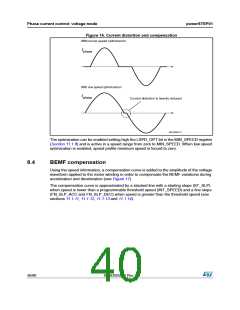
8.3
Low speed optimization
When the motor is driven at a very low speed using a small driving voltage, the resulting
phase current can be distorted. As a consequence, the motor position is different from the
ideal one (see Figure 16).
The device implements a low speed optimization in order to remove this effect.
DocID025022 Rev 1
39/90

 STMICROELECTRONICS [ ST ]