powerSTEP01
Phase current control: voltage mode
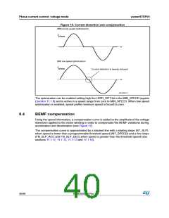
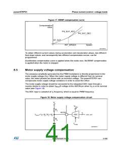
Figure 17. BEMF compensation curve
Compensation
value
FN_SLP_ACC
FN_SLP_DEC
Speed
ST_SLP
INT_SPEED
AM12835v1
To obtain different current values during acceleration and deceleration phase, two different
final slope values, and consequently two different compensation curves, can be
programmed.
Acceleration compensation curve is applied when the motor runs. No BEMF compensation
is applied when the motor is stopped.
8.5
Motor supply voltage compensation
The sinewave amplitude generated by the PWM modulators is directly proportional to the
motor supply voltage (VS). When the motor supply voltage is different from its nominal
value, the motor phases are driven with an incorrect voltage. The powerSTEP01 can
compensate motor supply voltage variations in order to avoid this effect.
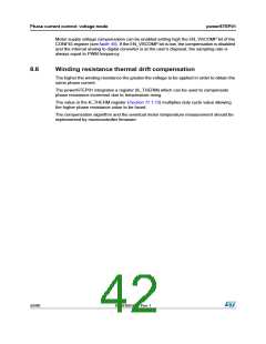
The motor supply voltage should be connected to the integrated ADC input through a
resistor divider in order to obtain VREG/2 voltage at the ADCIN pin when VS is at its nominal
value (see Figure 18).
The ADC input is sampled at fS frequency, which is equal to PWM frequency.
Figure 18. Motor supply voltage compensation circuit
VS
VREG
RA
ADCIN
5
VADCIN= V x R / (R + R)
ADC
ADC_OUT
S
B
A
B
R
B
fPWM
AM12836v1
DocID025022 Rev 1
41/90

 STMICROELECTRONICS [ ST ]