powerSTEP01
Phase current control: current mode
9
Phase current control: current mode
When the current mode driving is selected (CM_VM bit in STEP_MODE register is set to 1),
the powerSTEP01 performs a new current control technique, named predictive current
control, allowing the device to obtain the target average phase current. This method is
described in detail in Section 9.1. Furthermore, the powerSTEP01 automatically selects the
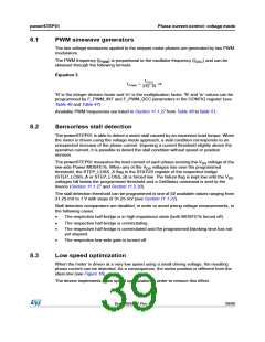
better decay mode in order to follow the current profile.
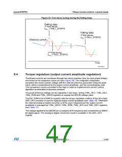
Current control algorithm parameters can be programmed by T_FAST, TON_MIN,
TOFF_MIN and CONFIG registers (see Section 11.1.11, 11.1.12, 11.1.19 and 11.1.27 for
details).
Different current amplitude can be set for acceleration, deceleration and constant speed
phases and when the motor is stopped through TVAL_ACC, TVAL_DEC, TVAL_RUN and
TVAL_HOLD registers (see Section 11.1.16). The output current amplitude can also be
regulated by the ADCIN voltage value (see Section 9.4).
Each bridge is driven by an independent control system that shares with the other bridge the
control parameters only.
9.1
Predictive current control
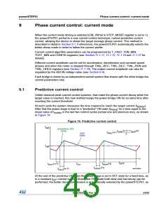
Unlike classical peak current control systems, that make the phase current decay when the
target value is reached, this new method keeps the power bridge ON for an extra time after
reaching the current threshold.
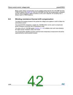
At each cycle the system measures the time required to reach the target current (tSENSE).
After that the power stage is kept in a “predictive” ON state (tPRED) for a time equal to the
mean value of tSENSE in the last two control cycles (actual one and previous one), as shown
in Figure 19.
Figure 19. Predictive current control
I
out
predictive ON
tSENSE (n-1) + tSENSE(n)
2
state
tPRED(n) =
OFF
state
I
ref
t
OFF
tSENSE (n-1)
tPRED(n)
SENSE (n)
tOFF
t
AM15048v1
t
PRED(n-1)
At the end of the predictive ON state the power stage is set in OFF state for a fixed time, as
in a constant tOFF current control. During the OFF state both slow and fast decay can be
performed; the better decay combination is automatically selected by the powerSTEP01, as
DocID025022 Rev 1
43/90

 STMICROELECTRONICS [ ST ]