NAND128-A, NAND256-A, NAND512-A, NAND01G-A
Page Program
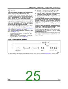
3. the data is then input (up to 528 Bytes/ 264
Words) and loaded into the Page Buffer
4. one bus cycle is required to issue the confirm
command to start the P/E/R Controller.
5. The P/E/R Controller then programs the data
into the array.
Once the program operation has started the Sta-
tus Register can be read using the Read Status
Register command. During program operations
the Status Register will only flag errors for bits set
to '1' that have not been successfully programmed
to '0'.
The Page Program operation is the standard oper-
ation to program data to the memory array.
The main area of the memory array is pro-
grammed by page, however partial page program-
ming is allowed where any number of bytes (1 to
528) or words (1 to 264) can be programmed.
The maximum number of consecutive partial page
program operations allowed in the same page is
three. After exceeding this a Block Erase com-
mand must be issued before any further program
operations can take place in that page.
During the program operation, only the Read Sta-
tus Register and Reset commands will be accept-
ed, all other commands will be ignored.
Once the program operation has completed the P/
E/R Controller bit SR6 is set to ‘1’ and the Ready/
Busy signal goes High.
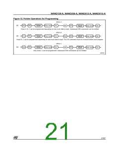
Before starting a Page Program operation a Point-
er operation can be performed to point to the area
to be programmed. Refer to the Pointer Opera-
tions section and Figure 12. for details.
Each Page Program operation consists of five
steps (see Figure 17.):
The device remains in Read Status Register mode
until another valid command is written to the Com-
mand Interface.
1. one bus cycle is required to setup the Page
Program command
2. four bus cycles are then required to input the
program address (refer to Table 6.)
Figure 17. Page Program Operation
tBLBH2
(Program Busy time)
RB
Busy
I/O
80h
Data Input
10h
Address Inputs
70h
SR0
Confirm
Code
Read Status Register
Page Program
Setup Code
ai07566
Note: Before starting a Page Program operation a Pointer operation can be performed. Refer to Pointer Operations section for details.
25/57

 STMICROELECTRONICS [ ST ]