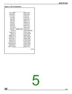
M59PW1282
COMMAND INTERFACE
All Bus Write operations to the memory are inter-
preted by the Command Interface. Commands
consist of one or more sequential Bus Write oper-
ations. Failure to observe a valid sequence of Bus
Write operations will result in the memory return-
ing to Read mode. The long command sequences
are imposed to maximize data security.
Refer to Tables 4 and 5, for a summary of the com-
mands.
As the device contains two internal memories care
must be taken to issue the commands to the cor-
vert to Read/Reset mode. The command requires
four Bus Write operations, the final write operation
latches the address and data in the internal state
machine and starts the P/E.C.
During the program operation the memory will ig-
nore all commands. It is not possible to issue any
command to abort or pause the operation. Typical
program times are given in Table 6. Bus Read op-
erations during the program operation will output
the Status Register on the Data Inputs/Outputs.
See the section on the Status Register for more
details.
rect address. To select the Top die (A22 = V ) or
IH
the Bottom die (A22 = V ) the A22 latch procedure
(see Figure 4) must be followed.
After the program operation has completed the
memory will return to the Read mode, unless an
error has occurred. When an error occurs the
memory will continue to output the Status Regis-
ter. A Read/Reset command must be issued to re-
set the error condition and return to Read mode.
Note that the Program command cannot change a
bit set at ’0’ back to ’1’.
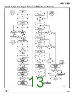
Multiple Word Program Command
The Multiple Word Program command can be
used to program large streams of data. It greatly
reduces the total programming time when a large
number of Words are written in the memory at
IL
It is not necessary to repeat the A22 latch proce-
dure if all the commands are issued to the same
die, unless the power supply V is switched off.
CC
Read/Reset Command.
The Read/Reset command returns the memory to
its Read mode where it behaves like a ROM or
EPROM, unless otherwise stated. It also resets
the errors in the Status Register. Either one or
three Bus Write operations can be used to issue
the Read/Reset command.
V
must be set to V
during the Read/Reset
PP
HH
once. V must be set to V during Multiple Word
PP
HH
command. If V is set to either V or V the com-
PP
IL
IH
Program. If V is set either V or V the com-
PP
IL
IH
mand will be ignored. The command can be is-
sued, between Bus Write cycles before the start of
a program operation, to return the device to read
mode. Once the program operation has started the
Read/Reset command is no longer accepted.
mand will be ignored, the data will remain un-
changed and the device will revert to Read mode.
It has four phases: the Setup Phase to initiate the
command, the Program Phase to program the
data to the memory, the Verify Phase to check that
the data has been correctly programmed and re-
program if necessary and the Exit Phase.
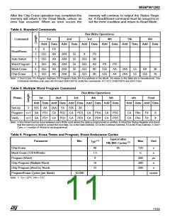
Setup Phase. The Multiple Word Program com-
mand requires three Bus Write operations to ini-
tiate the command (refer to Table 4, Multiple Word
Program Command and Figure 8, Multiple Word
Program Flowchart).
The Status Register must be read in order to
check that the P/E.C. has started (see Table 8 and
Figure 8).
Auto Select Command.
The Auto Select command is used to read the
Manufacturer Code and the Device Code. V
PP
must be set to V
during the Auto Select com-
HH
mand. If V is set to either V or V the com-
PP
IL
IH
mand will be ignored. Three consecutive Bus
Write operations are required to issue the Auto Se-
lect command. Once the Auto Select command is
issued the memory remains in Auto Select mode
until a Read/Reset command is issued, all other
commands are ignored.
From the Auto Select mode the Manufacturer
Code can be read using a Bus Read operation
Program Phase. The Program Phase requires
n+1 Bus Write operations, where n is the number
of Words, to execute the programming phase (re-
fer to Table 5, Multiple Word Program and Figure
7, Multiple Word Program Flowchart).
Before any Bus Write operation of the Program
Phase, the Status Register must be read in order
to check that the P/E.C. is ready to accept the op-
eration (see Table 8 and Figure 8).
with A0 = V and A1 = V . The other address bits
IL
IL
may be set to either V or V .
IL
IH
The Device Code can be read using a Bus Read
operation with A0 = V and A1 = V . The other
IH
IL
address bits may be set to either V or V .
IL
IH
Word Program Command.
The Word Program command can be used to pro-
gram a Word to the memory array. V must be
The Program Phase is executed in three different
sub-phases:
PP
set to V during Word Program. If V is set to ei-
HH
PP
ther V or V the command will be ignored, the
data will remain unchanged and the device will re-
1. The first Bus Write operation of the Program
Phase (the 4th of the command) latches the
IL
IH
9/24

 STMICROELECTRONICS [ ST ]