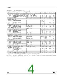
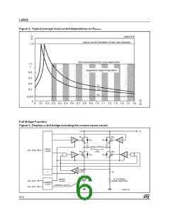
L9935
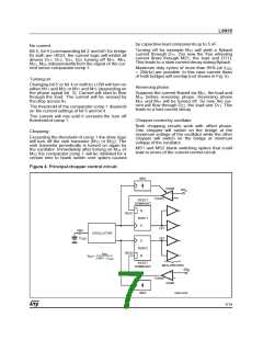
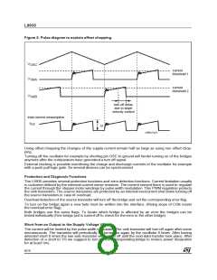
Figure 5. Pulse diagram to explain offset chopping.
V
OSC
current
threshold 1
V
V
SRA
SRB
current
threshold 2
turn off delay
due to slope
velocity control
total current consumption
I
VS
∆I
D99AT421
Using offset chopping the changes of the supply current remain half as large as using non offset chop-
ping.
Turning off the oscillator for example by shorting pin OSC to ground will hinder turning on of the bridges
anymore after the comparatorshave generateda turn off signal.
External clocking is possible overdriving the charge and discharge currents of the oscillator for example
with a push pull logic gate. So several devices can be synchronized.
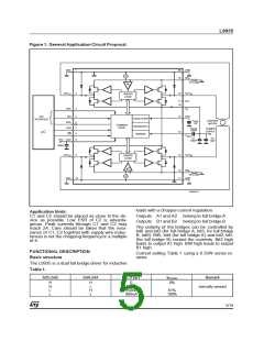
Protection and Diagnosis Functions
The L9935 provides several protection functions and error detection functions. Current limitation usually
is customerdefined by the external current sense resistors. The current sensed there is used to regulate
the current through the steppermotor windings by pulse width modulation. This PWM regulation protects
the sink transistors. The source transistors are protected by an internal overcurrent shut down turning off
the source transistors in case of overload.
Overload detection of the source transistor will turn off the bridge and set the corresponding error flag.
To turn on the bridge again a new byte must be written into the interface. (Rising slope of CSN resets
the overload error flag).
Both bridges use the same flags. To locate which bridge is affected by an error the bridges can be
tested individually (One bridge just is turned off to check for the error in the other bridge).
Short from an Output to the Supply Voltage VS
The current will be limited by the pulse width modulator. The sink transistor will turn off again after some
microseconds. The transistor will periodically be turned on again by the oscillator 8 times. After having
detected short 8 times the low side transistor will remain off until the next data transfer took place. After
detection of a short to VS we suggest to turn off the corresponding bridge to reduce power dissipation
for at least 1ms.
8/19

 STMICROELECTRONICS [ ST ]