L9935
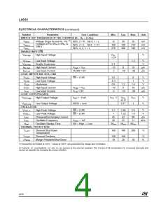
ELECTRICAL CHARACTERISTICS
(continued)
Symbol
Parameter
Test Condition
Min.
Typ.
Max.
Unit
SWITCH OFF THRESHOLD OF THE CHOPPER (R1 R = 0.33 )
Ω
2
2)
VSRHL
VSRLH
VSRLL
Voltage Drops Across R1 R2
(Voltage at Pin SRA or SRB vs.
GND)
Bit 5, 2 = H Bit 4, 1 = L
Bit 5, 2 = L Bit 4, 1 = H
Bit 5, 4, 2, 1 = L
12
20
35
mV
mV
mV
160
270
180
300
210
340
ENABLE INPUT EN
VEN High
High Input Voltage
VCC
-1.2V
V
VEN low
VEN Hyst
IEN High
IEN Low
Low Input Voltage
Enable Hysteresis
High Input Current
Low Input Current
1.2
V
V
0.1
-10
-3
VHigh = VCC
VLOW = 0V
0
10
A
A
µ
µ
-10
-30
LOGIC INPUTS SDI. SCK, CSN
VHIGH
VLOW
VHyst
IHIGH
ILow
High Input Voltage
Low Input Voltage
Hysteresis
EN = LOW
2.6
-0.3
0.8
-10
-3
8
V
1
V
V
1.2
0
1.6
10
-30
High Input Current
Low Input Current
VHigh = VCC
VLow = 0V
µA
µA
-10
LOGIC OUTPUTS (SDO)
VSDO,High High Output Voltage
ISDO = -1mA
ISDO = 1mA
VCC -1
VCC
-0.17
VCC
1
V
V
VSDO,Low
Low Output Voltage
0.17
OSCILLATOR
VOSC, H
VOSC, L
IOSC
High Peak Voltage
EN = LOW
EN = LOW
2.2
1
2.46
1.23
62
2.6
1.4
V
V
Low Peak Voltage
Charging/Discharging Current
Oscillator Frequency
45
80
µA
kHz
fOSC
COSC = 1nF
20
25
31
tStart
Oscillator Startup Time
EN = High
Low
2/fosc
5/fosc
8/fosc
→
THERMAL PROTECTION
TJ-OFF
Thermal Shut-Down
Temperature
160
180
200
30
°C
TJ-ALM
Thermal Prealarm
Margin Prealarm/Shut-Down
130
10
160
20
°C
∆TMGN
K
1) Parameters are tested at 125°C. Values at 140°C are guaranteed by design and correlation.
2) Currents of combinations LH and LL are sensed at the external resistors. The Current of bit combination HL is sensed internally and
cannot be adjusted by changing the sense resistors.
4/19

 STMICROELECTRONICS [ ST ]