L9935
Using 75mA chopping immediatelly after stand by:
The high resistive motor can be forced to chopping operation in the low current range. This leads to the
samebehaviouras using a low resistive motor.
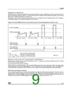
Short to VS detectionusing high resistive motors:
The short to VS flag is overwritten each time the chopper comparator responds. Having detected a short
this flagonly can be reset by reachingchopping operation or resetting the circuit (ENN=1). For a high re-
sistive motor thisleads to the following consequence: Once a short to VS is detected the error flag will
persist even if the short is removed again until either a reset (ENN=1) or chopping(for example in 75mA
mode) has taken place. We suggest to return to operation once a short to VS was detected by using the
low current mode to reset the flag.
Limitation of the Diagnosis
The diagnosis depends on either detecting an overcurrent of more than typically 1.8A through the
source transistor or on not detecting a flyback pulse, or on detecting severe overcurrents of the sink
transistorimmediately after turn on.
Small currents bypassing the load will not be detected.
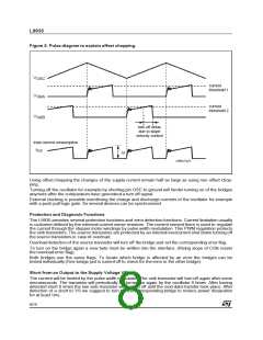
In the low current range (hold current) the flyback pulse (especially commutating against the supply
voltage after changing phase) may (depending on the inductivity of the stepper motor windings) be
too short to be detected correctly. For this reason diagnosis using the flyback pulse is blanked at
phase reversal at hold current.
In the low current range (hold current) the current capability of the bridge is reduced on purpose.
Short to VS may not be detected. In stead the bridge may just chop like normal operation.
Flyback pulse detection is not blanked during PWM regulation at hold current (here commutation
voltage is less than 1V thus providing a longer pulse duration.) This however should be taken in ac-
count using stepper motors with low inductivity (less than 0.5mH). Using motors with such a low in-
ductivity the flyback voltage in hold mode may decay too fast.
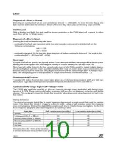
Motors with extremely low ohmic resistance tend to pump up the current because current decay dur-
ing flyback approaches zero while at bridge turn on the current will increase. This may lead to over-
current detection. We suggest to use stepper motors with an ohmic resistance of approximately 3Ω or
more.
Partial shorts of windings or shorts of stepper motors with coils in series may still yield a flyback pulses
that are accepted by the diagnosisas a proper signal.
Table 2. Error table.
Error 1
bit7
Error 2
bit6
Description
H
L
H
H
Normal operation
Short to VS (sink overload immediately after turn on)
shorted load (no flyback)
open load (no flyback)
H
L
L
L
short to gnd (source overload, missing flyback is masked)
overtemperature prealarm
At stepping rates faster than 1ms/data transfer error flags indicating a short should be used to initiate a
pause of at least 1ms to allow the power bridges to cool down again.
11/19

 STMICROELECTRONICS [ ST ]