L9935
by capacitiveload componentsup to 5 nF.
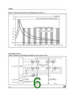
No current:
Turning off for example M12 will yield a flyback
current through D11. (So now the free wheeling
current flows through M21, the load and D11).
This leads to a slow current decay during flyback.
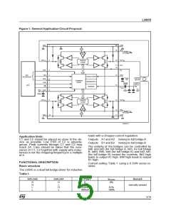
Maximum duty cycles of more than 85% (at fOSC
= 25kHz) are possible. In this case current flows
of both bridges will overlap (not shown in Fig. 5).
Bit 5, bit 4 (correspondingbit 2 and bit1 for bridge
B) both are HIGH, the current logic will inhibit all
drivers D11, D12, D21, D22 turning off M11, M12,
M21, M22 independentlyfrom the signal of the cur-
rent sense comparator comp 1.
Turning on:
Changing bit 5 or bit 4 or bothto LOW will turn on
either M11 and M22 orM21 and M12 (dependingon
the phase signal bit 3). Current will start to flow
through the load. The current will be sensed by
the drop across R1.
The threshold of the comparator comp 1 depends
on the current settings of bit 5 and bit 4.
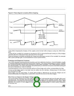
Reversing phase:
Suppose the current flowed via M21, the load and
M12 before reversing phase. Reversing phase
M21 and M12 will be turned off. So now the cur-
rent will flow through D22, the load and D11. This
leads to a fast current decay.
The current will rise until it exceeds the turn off
thresholdof comp 1.
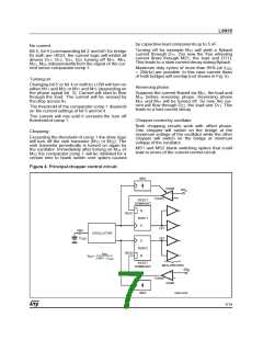
Chopper control by oscillator
Both chopping circuits work with offset phase.
One chopper will switch on the bridge at the
maximum voltage of the oscillator while the other
chopper will switch on the bridge at minimum
voltage of the oscillator.
MS1 and MS2 blank switching spikes that could
lead to errors of the current control circuit.
Chopping:
Exceeding the threshold of comp 1 the drive logic
will turn off the sink transistor (M12 or M22). The
sink transistor periodically is turned on again by
the oscillator. Immediately after turning on M12 or
M22 the comparator comp 1 will be inhibited for a
certain time to blank switch over spikes caused
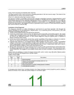
Figure 4. Principal chopper control circuit.
MS1
inhibit
SR
A
+
-
Comp1
RESET
DOMINANT
R
RES1
RSFF1
S
Dr1
Dr2
OSC
C
OSCILLATOR
OSC
S
RSFF2
R
iOSC
2.46V · COSC
RES2
fOSC=
RESET
DOMINANT
MOS DRIVERS
SR
B
+
-
Comp2
inhibit
MS2
D99AT420
7/19

 STMICROELECTRONICS [ ST ]