L9935
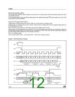
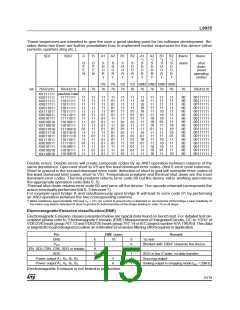
Test condition for all propagation times (unless otherwise specified)
HIGH ≥ 3V; LOW ≤ 0.8V;tr, tf = 10ns, Enable: ENN Low < 0.8V, ENN High > Vcc -0.8V
Symbol
fSCLK
t1
Parameter
SCK-Frequency
SCK stable before and after
CSN = 0
Test Conditions
Min.
DC
100
Typ.
Max.
2MHz
Unit
ns
tch
tcl
tsu
tsh
td
tzc
ten_sck
tpd
Width of SCK high pulse
Width of SCK low pulse
SDI setup time
SDI hold time
SDO delay time (CL = 50pF)
SDO high Z CSN high
Setup time ENABLE to SCK
Propagation delay SPI to
output QXX
200
200
80
ns
ns
ns
ns
ns
ns
µs
µs
80
100
100
HIGH > VCC -1.2V
30
2 (*)
(*) Measured at a transition from High impedance (Bridge off) to bridgeon. (Reversing polarity takes about 1µs longer because the bridge first
turns off before turning on in reverse direction).
Table of bits
bit5,bit4 : current range of bridge A (Outputs A1 and A2)
bit3
: polarityof bridge A
bit2,bit1 : current range of bridge B (Outputs B1 and B2)
bit0
: polarityof bridge B
bit7,bit6 : Error1 and Error 2
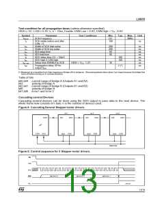
Cascading several Devices
Cascading several devices can be done using the SDO output to pass data to the next device. The
whole frame now consists of n byte. n is the number of devices used.
Figure 8. CascadingSeveral Stepper motor drivers.
no.1
no.2
no.3
SDO
SDI
SDO
SDI
SDO
SDI
SDO
µP
CSN SCK
CSN
CSN
CSN
SCK
SCK
SCK
D99AT438
Figure 9. Control sequence for 3 Stepper motor drivers.
EN
CSN
SCK
SDO
byte for no. 3
byte for no. 2
byte for no. 1
of µP
Q
D99AT439
XX
13/19

 STMICROELECTRONICS [ ST ]