L9935
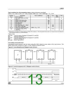
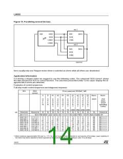
Figure 10. Paralleling several Devices.
no.1
no.2
SDI
SDO
SDI
SDO
SDO
SCK
CSN1
CSN2
SCK
CSN
µP
SDI
SCK
CSN
D99AT440
here usually only one Steppermotor driver is selected at a time while all others are deselected.
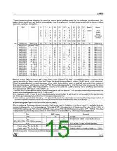
Application Information
For driving a steppermotor we suggest to use the following codes. The columned ’SDO correct’ shows
the data returned at SDO in correct function. The columnes presented under ’Error cases’ display the di-
agnosis bits if errors are detected.
Examples of control sequences
Full step mode control sequencesand diagnosis response.
SDI
SDO
Error cases and SDObit7, bit6
correct
A
B
A1
A2
B1
B2
A1
*)
S
H
O
R
T
A2
*)
S
H
O
R
T
B1
*)
S
H
O
R
T
B2 therm.
*)
therm.
O
P
E
N
O
P
E
N
S
H
O
R
T
S
H
O
R
T
S
H
O
R
T
S
H
O
R
T
S
H
O
R
T
alarm
shut
down
(reset
operating
codes)
VS VS VS VS GND GND GND GND
76 76 76 76 76 76 76 76
bit
76543210
XX111111
76543210
76
76
76
76543210
SDO PRESENT LAST DATA OR 11111111 IN CASE PREV. STATE WAS STAND BY
11
10
10
01
11
10
10
01
11
11
11
10
10
01
11
10
00
00
00
00
00
00
00
00
00111111
00111111
00111111
00111111
00111111
00111111
00111111
00111111
XX011011
XX010011
XX010010
XX011010
XX011011
XX010011
XX010010
XX011010
11111111
11011011
11010011
11010010
11011010
11011011
11010011
11010010
11
11
01
11
01
11
01
11
11
11
11
01
11
01
11
01
11
11
01
01
01
11
01
01
11
01
01
11
01
01
01
11
11
11
11
01
01
01
11
01
11
01
01
01
11
01
01
01
11
10
01
11
10
10
01
11
11
11
10
10
01
11
10
10
*) Motor resistance approximatelly 10Ω and VS = 12V. So a short to ground only is detected on one branche of the bridge. Lower resistivity of
the motor may lead to detection of short to ground on both branches of the bridge leading to code 10 on all steps.
14/19

 STMICROELECTRONICS [ ST ]