L7250
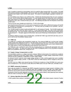
2.7.2 Open Loop Commutation
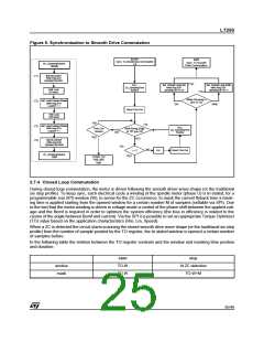
After position sense is complete, the microcontroller commutates the motor following a constant acceleration
profile until sufficient BEMF is developed to reliably measure it.
The starting position of the open loop commutation, determined by the position sense routine, is set up by first
initializing the Memory Address Counter using LOADCP (*1), then clocking ADVANCE (*2) the appropriate
number of times (8 pulses per 6 state position). The spindle state will be OLCOAST while setting the initial state.
Then, drivers are enabled in either OL_SIX or OL_SIN modes (*3) , depending on whether 6 state or sine mode
open loop commutation is desired. Once the motor is accelerated up to an appropriate speed (*4) , the motor
is tri-stated by transitioning to the OLCOAST (*5) and then CLCOAST states, as described below, to synchro-
nize the Smoothdrive system to the motor.
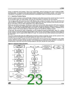
Figure 5. Open Loop Commutation
START
Open Loop Commutation
Nadv=0 , i=0
EXIT
Open Loop
Commutation
Note1: Spstate[3:0] condition has
been set in OLCOAST
by the Inductive Sense
Routine
Set Load Coarse Phase
Write Reg.07H
(*1)
(*2)
Set OLCOAST
Write Reg.03H
Spstate[3:0]=0001
(*5)
(*4)
LoadCP = 1
Set ADVANCE
Write Reg.07H
Advance = 1
i = RAMP_Steps
Inc Nadv
Inc i
Note2: Nalign is received from
the Inductive Sense routine
Indicating the rotor position
alignement
Nadv=Nalign
Wait the End of
RAMP_DELAY[ i ]
Set Open Loop SIX
Write Reg.03H
Spstate[3:0] =0010
SIX
Accelerate in
Sine or Six
(*3)
Set ADVANCE
Write Reg.07H
Advance = 1
Set Open Loop SINE
Write Reg.03H
SINE
Spstate[3:0] =0011
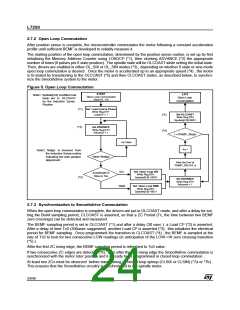
2.7.3 Synchronization to Smoothdrive Commutation
When the open loop commutation is complete, the drivers are put in OLCOAST mode, and after a delay for set-
ting the Bemf sampling period, CLCOAST is asserted, so that a ZC Period (Tc, the time between two BEMF
zero crossings) can be detected and measured.
The BEMF sampling period is set in OLCOAST (*1) and after a delay (30 usec ) a Load CP (*2) is asserted.
After a delay of time Tc0 (300usec suggested) another Load CP is asserted (*3); this initializes the electrical
period for BEMF sampling. Once pregrammed the transition to CLCOAST (*4) , the BEMF is sampled at the
rate of Tc0 to look for two consecutive LOW readings (in anticipation of the LOW->HI zero crossing transition
(*5) ).
After the first ZC rising edge, the BEMF sampling period is refreshed to Tc0 value.
If two consecutive ZC edges are detected (*6), then after the last rising edge the Smoothdrive commutation is
synchronized with the motor rotor position and it is ready to be programmed in closed loop commutation .
At least two ZCs must be observed before transitioning to closed loop spinup (CLSIX or CLSIN) (*7a or *7b) .
This ensures that the Smoothdrive circuitry is synchronized to the spindle motor.
24/46

 STMICROELECTRONICS [ ST ]