L7250
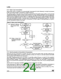
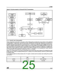
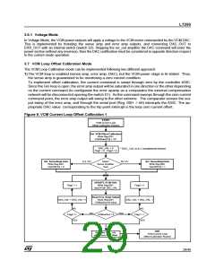
Figure 6. Synchronization to Smooth Drive Commutation
START
EXIT
Sync. To Smooth
Drive Commutation
Sync. To SmoothDrive Commutation
ZC_SamplingRoutine
i=0
BEGIN
Set OLCOAST
Write Reg.03H
(*1)
Spstate[3:0]=0001
(*7a)
CALL
ZC_SamplingTime
Routine
Set Closed Loop SIX
Write Reg.03H
Spstate[3:0] =0110
Set Closed Loop SINE
Write Reg.03H
Spstate[3:0] =0111
Wait Loop
(30 usec)
(*7b)
Motor Running in
Sine or Six
Set Load Coarse Phase
Write Reg.07H
(*2)
SINE
SIX
LoadCP = 1
Reset Time Out
Wait Loop
(300 usec)
NO
(*5)
Wait Rising Edge
Set Load Coarse Phase
Write Reg.07H
(*3)
(*4)
CALL
ZC_SamplingTime
Routine
Time Out
Control
LoadCP = 1
ZC
of
(pin 22)
NO
YES
YES
Set CLCOAST
Write Reg.03H
Spstate[3:0]=0000
(*6)
NO
Inc i
Reset Time Out
i = 2
ZC_SamplingRoutine
YES
END
START UP
FAILURE
Exit
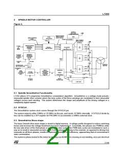
2.7.4 Closed Loop Commutation
During closed loop commutation, the motor is driven following the smooth driver wave shape (or the traditional
six step profile). To keep sync, each electrical cycle a winding of the spindle motor (phase U) is tri-stated, for a
programmable (via SPI) window (W), to sense for the ZC occurrence; to mask the current flyback time a mask-
ing time is applied starting from the opened window for a certain number M of samples (settable via SPI). Due
to the fact that the motor winding is driven in voltage mode a control of the phase shift between the applied volt-
age and the Bemf is required in order to optimize the system efficiency (the loss in efficiency is related to the
cosine of the angle between Bemf and current). Via the SPI it is possible to set an appropriate Torque Optimizer
(TO) value based on the application characteristics (Rm, Lm, Speed).
When a ZC is detected the circuit starts scanning the stored smooth drive wave shape (or the traditional six step
profile) from the number of sample pointed by the TO register; the tri-stated window is opened a certain number
of samples before.
In the following table the relation between the TO register contents and the window and masking time position
and duration:
start
TO-W
TO-W
stop
window
mask
At ZC detection
TO-W+M
25/46

 STMICROELECTRONICS [ ST ]