L7250
cycle. A window is opened up in that winding, and it is tri-stated to allow sensing of the zero crossing. The width
of the window opening is programmable, and can be made very small in steady state. A frequency locked loop
keeps the wave shape in sync with the motor speed. The system is entirely digital, requiring no external com-
ponents.
The Smoothdrive wave shape is sync with the motor. It divides the electrical period, from one zero crossing to
the next, into 48 evenly spaced sample periods. For each sample period, the driving duty cycle is defined for
each motor phase by a table in the Smoothdrive logic. The Memory Address Counter sequences the samples
through the cycle, and is clocked N times per cycle. The following describes how the frequency locked loop
system works:
There are N sine wave samples per electrical rev. N=48 for this design.
Each electrical period (from one ZC to the next) is measured by a timer with an effective frequency of Fsysclk/
48, resulting in a measured zero crossing period Tc. The timer does not actually run at Fsysclk/48 - the reso-
lution is more like Fsysclk/3.
The FSCAN Counter is a down counter preloaded with Tc, and running at Fsysclk. The FSCAN Counter puts
out a pulse each time it hits zero, then it resets to Tc and counts down again. This cycle occurs N (48) times
per electrical cycle. Thus, the FSCAN Counter divides the electrical cycle into N evenly spaced samples based
on the previous Tc. The pulse signal out of this block, that occurs 48 times per electrical period, is called FS-
CAN.
The Memory Address Counter counts FSCAN pulses, and tells the Profile Logic which full scale duty cycle val-
ues to use for each Smoothdrive sample period.
2.4 PWM rate
The PWM rate is unrelated to the Smoothdrive sample rate. The minimum PWM rate is 32.2kHz with 16.5MHz
spindle system clock, defined by (Fsys/512). The spin system clock is SYSCLK or SYSCLK/2, chosen via serial
port (SYSCLK/2 is the default at power up). 9 bits of resolution define the duty cycle at each sample period.
The PWM counter is reset at the beginning of each electrical cycle (at the ZC).
The PWM duty cycle is defined for each of the two chopping phases by comparing the appropriate duty cycle
values to the counter. The duty cycle values are the result of multiplying values in the Smoothdrive waveform
table by the amplitude value KVAL coming from SPI.
2.5 Supply Voltage Compensation via ADC
The Smoothdrive system is a voltage mode drive scheme. Without compensation, the spindle drive amplitude
would be a proportion of the motor supply voltage. L7250 implements a supply voltage compensation scheme
whereby the drive amplitude is indipendent on motor supply voltage.
An internal 6 bit ADC reads the motor supply voltage variation (+/-10%), and the applied duty cycle is modified
to keep the applied voltage constant. A side effect is that the PWM frequency will be changed as well as the
duty cycle.
The ADC runs on a 4MHz clock derived from the SYSCLK (it is divided by 8 if the PRESMO bit is set to zero
else it is divided by 4). The conversion results affects the PWM counter once per PWM cycle, nominally 32 kHz.
2.6 BEMF comparator Hysteresis
Since only one polarity ZC is detected, the BEMF comparator hysteresis no longer needs to contribute a time
offset. The hysteresis is zero on the significant edge, and is engaged on the other edge. Thus, larger values of
hysteresis can be used to provide noise immunity at low speed while coasting, without affecting ZC timing.
Hysteresis of 50mV provides adeguate sensitivity for detecting motion startup, while improving noise immunity
when the motor is moving very slow or is stationary.
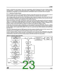
2.7 Startup Algorithm Description
L7250's spindle motor startup is controlled by firmware, and consists of four distinct phases: Inductive Position
22/46

 STMICROELECTRONICS [ ST ]