A d v a n c e I n f o r m a t i o n
Table 8. Burst Initial Access Delay
Initial Burst Access
(CLK cycles)
CR13
CR12
CR11
CR10
54D, 64C, 65A, 75E
0
0
0
0
0
0
0
0
0
0
0
0
1
1
1
1
0
0
1
1
0
0
1
1
0
1
0
1
0
1
0
1
2
3
4
5
6
7
8
9
1st CLK
2nd CLK
3rd CLK
4th CLK
5th CLK
CLK
ADV#
Address 1 Latched
Valid Address
Addresses
Three CLK Delay
3
DQ31-DQ0
D0
D1
D0
D2
D1
D3
D2
D4
D3
Four CLK Delay
4
DQ31-DQ0
Five CLK Delay
5
D0
D1
D2
DQ31-DQ0
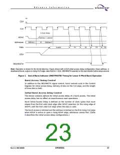
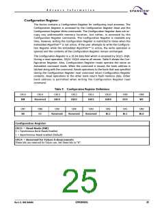
Figure 3. Initial Burst Delay Control
Notes:
1. Burst access starts with a rising CLK edge and when ADV# is active.
2. Configurations register 6 is always set to 1 (CR6 = 1). Burst starts and data outputs on the rising CLK edge.
3. CR [13-10] = 1 or three clock cycles
4. CR [13-10] = 2 or four clock cycles
5. CR [13-10] = 3 or five clock cycles
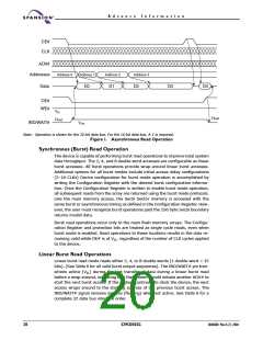
Burst CLK Edge Data Delivery
The device delivers data on the rising of CLK. Bit 6 in the Control Register (CR6)
is set to 1, and is the default configuration.
Burst Data Hold Control
The device is capable of holding data for one CLKs. The default configuration is
to hold data for one CLK and is the only valid state.
Asserting RESET# During A Burst Access
If RESET# is asserted low during a burst access, the burst access is immediately
terminated and the device defaults back to asynchronous read mode. Refer to
RESET#: Hardware Reset Pin for more information on the RESET# function.
24
S29CD032G
30606B0 March 22, 2004

 SPANSION [ SPANSION ]