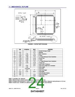
11 MECHANICAL OUTLINE
FIGURE 9 - 100 PIN TQFP PACKAGE
MIN
~
NOMINAL
MAX
1.60
0.15
1.45
14.20
7.10
12.20
14.20
7.10
12.20
0.20
0.75
~
REMARK
Overall Package Height
Standoff
A
A1
A2
D
D/2
D1
E
E/2
E1
H
~
~
0.05
1.35
13.80
6.90
11.80
13.80
6.90
11.80
0.09
0.45
~
1.40
14.00
7.00
12.00
14.00
7.00
12.00
~
0.60
1.00
0.40 Basic
3.5o
0.16
~
Body Thickness
X Span
1/2 X Span Measure from Centerline
X body Size
Y Span
1/2 Y Span Measure from Centerline
Y body Size
Lead Frame Thickness
Lead Foot Length from Centerline
Lead Length
Lead Pitch
Lead Foot Angle
Lead Width
Lead Shoulder Radius
Lead Foot Radius
Coplanarity
L
L1
e
0o
0.13
0.08
0.08
~
7o
0.23
~
0.20
0.08
θ
W
R1
R2
ccc
~
~
Note 1: Controlling Unit: millimeter
Note 2: Minimum space between protrusion and an adjacent lead is .007 mm.
Note 3: Package body dimensions D1 and E1 do not include the mold protrusion. Maximum mold protrusion is 0.25 mm
Note 5: Details of pin 1 identifier are optional but must be located within the zone indicated.
SMSC DS – USB97CFDC2-01
Page 24
Rev. 02-27-07
DATASHEET

 SMSC [ SMSC CORPORATION ]