10 USB PARAMETERS
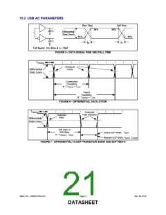
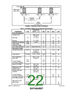
The following tables and diagrams were obtained from the USB specification
10.1 USB DC PARAMETERS
1.0
0.8
0.6
0.4
0.2
0.0
0.0 0.2 0.4 0.6 0.8 1.0 1.2 1.4 1.6 1.8 2.0 2.2 2.4 2.6 2.8 3.0 3.2
Common Mode Input Voltage (volts)
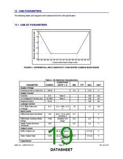
FIGURE 4 - DIFFERENTIAL INPUT SENSITIVITY OVER ENTIRE COMMON MODE RANGE
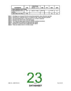
Table 4 - DC Electrical Characteristics
CONDITIONS
PARAMETER
Supply Voltage
SYMBOL
(NOTE 1, 2)
MIN
TYP
MAX
UNIT
Powered (Host or Hub) Port
Supply Current
VBUS
4.4
5.25
V
Function
ICC
ICCINIT
ICCS
Note 4
Note 5
100
100
100
mA
uA
uA
Un-configured Function (in)
Suspend Device
Leakage Current
Hi-Z State Data Line
Leakage
ILO
0 V < VIN < 3.3
V
-10
10
uA
Input Levels
Differential Input Sensitivity
VDI
VCM
VSE
|(D+) - (D-)|, and
FIGURE 4
0.2
0.8
0.8
V
V
V
Differential Common Mode
Range
Includes VDI
range
2.5
2.0
Single Ended Receiver
Threshold
Output Levels
Static Output Low
VOL
VOH
0.3 (3)
3.6 (3)
V
V
RL of 1.5 KΩ to
3.6 V
Static Output High
2.8
RL of 15 KΩ to
GND
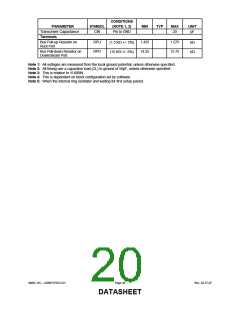
Capacitance
SMSC DS – USB97CFDC2-01
Page 19
Rev. 02-27-07
DATASHEET

 SMSC [ SMSC CORPORATION ]