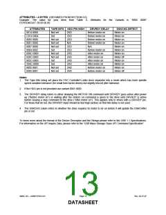
ATTRIBUTES – 4 BYTES (OBTAINED FROM SECTION 3.0)
Example: The value for your drive from Table 3- Attributes for the Variants is “0005 0000”
EEPROM.DAT: 00 05 00 00
ATTRIBUTES
0014 0000
TAPE BITS HDO PIN HIGH
DRVRDY DELAY
Before motor on
Before motor on
Before motor on
Before motor on
N/A
DSKCHG DETECT
Motor on
Not set
Set
2HD
2DD
2DD
N/A
C014 0004
0005 0000
0001 0000
0087 0000
8004 0002
000C 0000
020C 0000
802C 0000
33AC 0000
0005 0001
0405 0001
Motor on
Not set
Not set
Not set
Set
Motor on
Motor on
2DD
2DD
2HD
2HD
2HD
2HD
2HD
2HD
Motor on
Before motor on
After motor on
After motor on
After motor on
After motor on
Before motor on
Before motor on
Motor on
Not set
Not set
Set
Motor on
Motor off
Motor on
Set
Motor on
Not set
Not set
Motor on
Motor off
Notes:
1. The Tape Bits being set place the FDC Controller’s data clock separator into a mode which has more spindle
speed variation tolerance (for small form factor drives) but slightly less bit jitter tolerance.
2. If the HDO pin is not provided use variant 0001 0000.
3. The DRVRDY delay refers to either delaying the MOTOR ON command until DRVRDY goes active after power
up (“Before motor on”) or waiting after the motoro on command is given to the drive until DRVRDY is active
before issuing a step command to the drive (“After motor on”). This applies only to drives with a DRVRDY pin.
For those that do not, the DRVRDY input should be tied high (active) so that this delay is not used.
4. The DSKCHG colum refers to whether the drive requires its motor to be on before it will update the DSKCHNG
pin or not.
To know more about the format of the Device Descriptor and the Strings please refer to the USB 1.1 Specifications.
For information on the UFI Inquiry Data, please refer to the “USB Mass Storage Class UFI Command Specification”.
SMSC DS – USB97CFDC2-01
Page 13
Rev. 02-27-07
DATASHEET

 SMSC [ SMSC CORPORATION ]