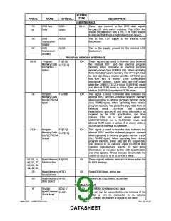
BUFFER
TYPE
PIN NO.
NAME
SYMBOL
USB-
DESCRIPTION
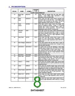
USB INTERFACE
59
61
USB Bus
Data
IO-U
These pins connect to the USB data signals
through 33 ohm series resistors. The USB+ line
should be pulled up with a 5%, 1.5K ohm resistor
to indicate that this is a high speed USB device.
USB+
58
62
USB
Transceiver
Supply
AVDD
This is the 3.3V supply to the internal USB
transceiver.
USB
Transceiver
Ground
AGND
This is the supply ground for the internal USB
transceiver.
PROGRAM MEMORY INTERFACE
FD[3:0]/ IO8 These signals are used to transfer data between
OPT[3:0]
38-35
Program
Memory Data
Bus/Option
Select
the internal 8051 and the external program
memory when operating in external program
memory mode (See ROMEN pin). When operating
from internal program memory, the OPT3 pin must
be tied high thru a resistor and the OPT[2:0] pins
tied low thru
a
resistor (See configuration
description section). These pins are not driven
while the USB97CFDC2-01 is in SUSPEND mode
and internal ROM mode is active. They are driven
while in SUSPEND in external ROM mode..
34
Program
FD4/IN0
IO8
This signal is used to transfer data between the
internal 8051 and the external program memory
when operating in external program memory mode
(See ROMEN pin). When operating from internal
program memory, this pin is the input data from an
Memory Data
Bus/EEPROM
Input
external
serial
EEPROM
that
contains
manufacturer specific ID and string information, as
required by the USB specification, and drive
options. This pin is not driven while the
USB97CFDC2-01 is in SUSPEND mode and
internal ROM mode is active. It is driven while in
SUSPEND in external ROM mode...
33-31
Program
FD[7:5]/
IO8
This signal is used to transfer data between the
internal 8051 and the external program memory
when operating in external program memory mode
(See ROMEN pin). When operating from internal
program memory, these pins are the output data
and strobes to an external serial EEPROM that
contains manufacturer specific ID and string
information, as required by the USB specification,
and drive options. These pins are driven while the
USB97CFDC2-01 is in SUSPEND mode.
Memory Data
Bus/EEPROM
Output
OUT[2:0]
50, 53, 54, Flash Memory FA[15:0]
49, 57, 29, Address Bus
56, 55, 48-
O8
These signals address memory locations within the
FLASH memory.
44, 42-40,
28
Flash Memory nFRD
Read Strobe
O8
O8
Flash ROM Read; active low
30
Flash Memory nFCE
Chip Select
Flash ROM Chip Select; active low
MISCELLANEOUS
17
Crystal
Input/External
Clock Input
XTAL1/
CLKIN
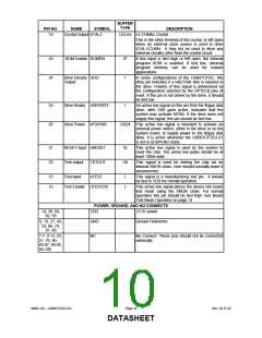
ICLKx 14.318Mhz Crystal or clock input.
This pin can be connected to one terminal of the
crystal or can be connected to an external
14.318Mhz clock when a crystal is not used.
SMSC DS – USB97CFDC2-01
Page 9
Rev. 02-27-07
DATASHEET

 SMSC [ SMSC CORPORATION ]