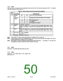
7.3.5 CR04
CR04 can only be accessed in the configuration state and after the CSR has been initialized to 04H. The default
value after power up is 00H (Table 29).
Table 29 - CR04: Parallel and Serial Extended Setup Register
BIT
NO.
BIT NAME
DESCRIPTION
1,0
Parallel
Bit 1
0
Bit 0
0
If CR1 bit 3 is a low level then:
Port
Extended
Modes
Standard and Bi-directional Modes (SPP) (default)
0
1
1
1
0
1
EPP Mode and SPP
ECP Mode2
ECP Mode & EPP Mode1,2
2,3
4
Reserved
MIDI 13
. Reserved – Read as 0
Serial Clock Select Port 1: A low level on this bit, disables MIDI support, clock =
divide by 13 (default). A high level on this bit enables MIDI support, clock = divide
by 12.
Serial Clock Select Port 2: A low level on this bit, disables MIDI support, clock =
divide by 13 (default). A high level on this bit enables MIDI support, clock = divide
by 12.
5
MIDI 23
6
7
EPP Type
Reserved
0 = EPP 1.9 (default)
1 = EPP 1.7
Reserved - Read as 0.
Note1: In this mode, EPP can be selected through the ecr register of ECP as mode 100.
Note2: In these modes, 2 drives can be supported directly, 3 or 4 drives must use external 4 drive support. SPP can be
selected through the ecr register of ECP as mode 000.
Note3: MIDI Support: The Musical Instrumental Digital Interface (MIDI) operates at
31.25Kbaud (+/-1%) which can
be derived from 125KHz. (24 MHz/12=2 MHz, 2 MHz/16=125 KHz).
7.3.6
CR05
(Reserved). The default value after power up is 00H .
7.3.7 CR06
(Reserved). The default value of this register after
power up is FFH.
SMSC DS – SP37E760
Page 50
Rev. 04/13/2001

 SMSC [ SMSC CORPORATION ]