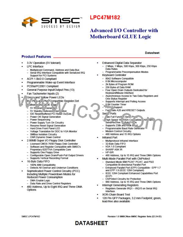
Advanced I/O Controller with Motherboard GLUE Logic
Datasheet
7
1
6
1
5
4
3
2
1
0
DRIVE WDATA RDATA WGATE
MOT
MOT
SEL0 TOGGLE TOGGLE
EN1
EN0
RESET
COND.
1
1
0
0
0
0
0
0
BIT 0 MOTOR ENABLE 0
Active high status of the MTR0 disk interface output pin. This bit is low after a hardware reset and
unaffected by a software reset.
BIT 1 MOTOR ENABLE 1
Active high status of the MTR1 disk interface output pin. This bit is low after a hardware reset and
unaffected by a software reset.
BIT 2 WRITE GATE
Active high status of the WGATE disk interface output.
BIT 3 READ DATA TOGGLE
Every inactive edge of the RDATA input causes this bit to change state.
BIT 4 WRITE DATA TOGGLE
Every inactive edge of the WDATA input causes this bit to change state.
BIT 5 DRIVE SELECT 0
Reflects the status of the Drive Select 0 bit of the DOR (address 3F2 bit 0). This bit is cleared after a
hardware reset and it is unaffected by a software reset.
BIT 6 RESERVED
Always read as a logic “1”.
BIT 7 RESERVED
Always read as a logic “1”
PS/2 Model 30 Mode
7
6
5
4
3
2
1
0
nDRV2 nDS1
nDS0 WDATA RDATA WGATE nDS3
nDS2
F/F
0
F/F
0
F/F
0
RESET
COND.
N/A
1
1
1
1
BIT 0 nDRIVE SELECT 2
The DS2 disk interface is not supported.
SMSC LPC47M182
41
Revision 1.8 SMSC/Non-SMSC Register Sets (02-24-05)
DATASHEET

 SMSC [ SMSC CORPORATION ]