Advanced I/O Controller with Motherboard GLUE Logic
Datasheet
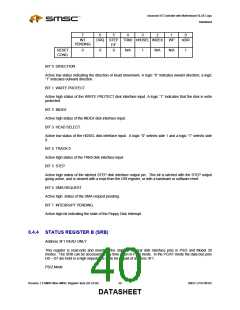
7
6
5
4
3
2
1
0
INT
DRQ STEP TRK0 nHDSEL INDEX
WP
nDIR
PENDING
F/F
RESET
COND.
0
0
0
N/A
1
N/A
N/A
1
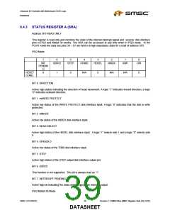
BIT 0 DIRECTION
Active low status indicating the direction of head movement. A logic “0” indicates inward direction; a logic
“1” indicates outward direction.
BIT 1 WRITE PROTECT
Active high status of the WRITE PROTECT disk interface input. A logic “1” indicates that the disk is write
protected.
BIT 2 INDEX
Active high status of the INDEX disk interface input.
BIT 3 HEAD SELECT
Active low status of the HDSEL disk interface input. A logic “0” selects side 1 and a logic “1” selects side
0.
BIT 4 TRACK 0
Active high status of the TRK0 disk interface input.
BIT 5 STEP
Active high status of the latched STEP disk interface output pin. This bit is latched with the STEP output
going active, and is cleared with a read from the DIR register, or with a hardware or software reset.
BIT 6 DMA REQUEST
Active high status of the DMA request pending.
BIT 7 INTERRUPT PENDING
Active high bit indicating the state of the Floppy Disk Interrupt.
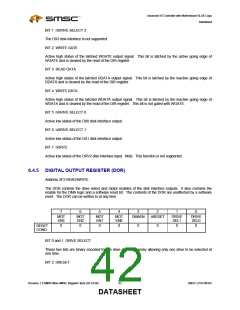
6.4.4 STATUS REGISTER B (SRB)
Address 3F1 READ ONLY
This register is read-only and monitors the state of several disk interface pins in PS/2 and Model 30
modes. The SRB can be accessed at any time when in PS/2 mode. In the PC/AT mode the data bus pins
D0 – D7 are held in a high impedance state for a read of address 3F1.
PS/2 Mode
Revision 1.8 SMSC/Non-SMSC Register Sets (02-24-05)
40
SMSC LPC47M182
DATASHEET

 SMSC [ SMSC CORPORATION ]