Advanced I/O Controller with Motherboard GLUE Logic
Datasheet
+5VTR
+12
1k
1k
1k
PWRGD_PS
nSLP_S3
BACKFEED_CUT
nBACKFEED_CUT
SMSC I/O
+12
nSLP_S5
LATCHED_B
F_CUT
470
ohms
+5VTR
1k
470
ohms
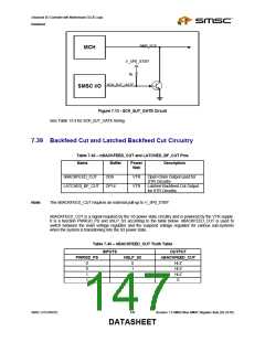
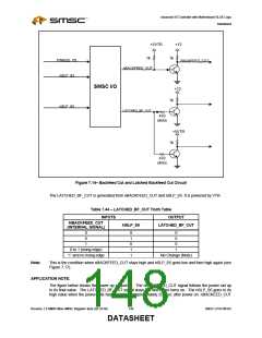
Figure 7.14– Backfeed Cut and Latched Backfeed Cut Circuit
The LATCHED_BF_CUT is generated from nBACKFEED_CUT and nSLP_S5. It is powered by VTR.
Table 7.44 – LATCHED_BF_CUT Truth Table
INPUTS
OUTPUT
NBACKFEED_CUT
NSLP_S5
LATCHED_BF_CUT
(INTERNAL SIGNAL)
0
0
1
0
1
0
1
1
0
0
0
1
0 to 1 (rising edge)
‘1’ and no rising edge
No Change (Note)
Note:
This is the condition when nBACKFEED_CUT stays high and nSLP_S5 goes low and then high again (see
Figure 7.17).
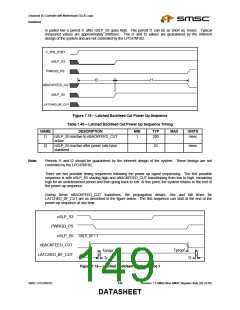
APPLICATION NOTE:
The figure below shows the power up sequence. The nBACKFEED_CUT signal follows the power rail up
to its final value. The LATCHED_BF_CUT signal stays low and never turns on. The nSLP_S5 goes to its
high value when the power rails have stabilized, approximately 25msec after power on. nBACKEED_CUT
Revision 1.8 SMSC/Non-SMSC Register Sets (02-24-05)
148
SMSC LPC47M182
DATASHEET

 SMSC [ SMSC CORPORATION ]