Advanced I/O Controller with Motherboard GLUE Logic
Datasheet
14us
~~
6us
8042
P20
KRST
nKBDRST
KRST_GA20
configuration register
Bit 2
P92
nALT_RST
Bit 0
Pulse
Gen
14us
Note: When Port 92 is
disabled, writes are
ignored and reads return
undefined values.
~
~
6us
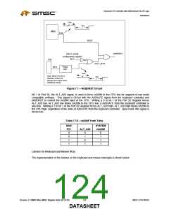
Figure 7.1 – NKBDRST Circuit
Bit 1 of Port 92, the ALT_A20 signal, is used to force nA20M to the CPU low for support of real mode
compatible software. This signal is OR’ed with the A20GATE signal from the keyboard controller and
nKBDRST to control the nA20M input of the CPU. Writing a 0 to bit 1 of the Port 92 Register forces
ALT_A20 low. ALT_A20 low drives nA20M to the CPU low, if A20GATE from the keyboard controller is
also low. Writing a 1 to bit 1 of the Port 92 Register forces ALT_A20 high. ALT_A20 high drives nA20M to
the CPU high, regardless of the state of A20GATE from the keyboard controller. Upon reset, this signal is
driven low.
Table 7.15 – nA20M Truth Table
8042
P21
0
0
1
SYSTEM
ALT_A20
nA20M
0
1
0
1
0
1
1
1
1
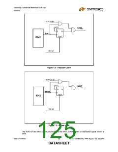
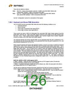
Latches On Keyboard and Mouse IRQs
The implementation of the latches on the keyboard and mouse interrupts is shown below.
Revision 1.8 SMSC/Non-SMSC Register Sets (02-24-05)
124
SMSC LPC47M182
DATASHEET

 SMSC [ SMSC CORPORATION ]