BIT 2 - 7 RESERVED
Should be set to a logical "0"
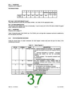
PS/2 Model 30 Mode
7
6
5
4
3
2
1
0
NOPREC DRATE DRATE
SEL1
1
SEL0
0
RESET
COND.
N/A
N/A
N/A
N/A
N/A
N/A
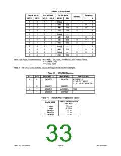
BIT 0 and 1 DATA RATE SELECT 0 and 1
These bits determine the data rate of the floppy controller. See Table 9 for the appropriate values.
BIT 2 NO PRECOMPENSATION
This bit can be set by software, but it has no functionality. It can be read by bit 2 of the DSR when in Model 30 register
mode. Unaffected by software reset.
BIT 3 - 7 RESERVED
Should be set to a logical "0"
Table 10 shows the state of the DENSEL pin. The DENSEL pin is set high after a hardware reset and is unaffected by
the DOR and the DSR resets.
6.5.2
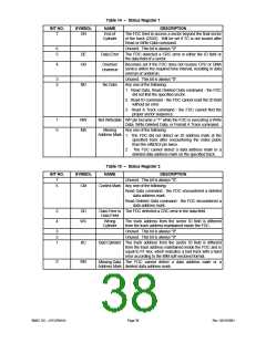
STATUS REGISTER ENCODING
During the Result Phase of certain commands, the Data Register contains data bytes that give the status of the
command just executed.
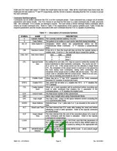
Table 13 – Status Register 0
BIT NO.
SYMBOL
NAME
DESCRIPTION
7,6
IC
Interrupt Code 00 - Normal termination of command. The specified
command was properly executed and completed without
error.
01 - Abnormal termination of command. Command
execution was started, but was not successfully
completed.
10 - Invalid command. The requested command could
not be executed.
11 - Abnormal termination caused by Polling.
5
4
SE
EC
Seek End
The FDC completed a Seek, Relative Seek or
Recalibrate command (used during a Sense Interrupt
Command).
Equipment
Check
The TRK0 pin failed to become a "1" after:
1. 80 step pulses in the Recalibrate command.
2. The Relative Seek command caused the FDC to
step outward beyond Track 0.
3
2
1,0
Unused. This bit is always "0".
Head Address The current head address.
Drive Select The current selected drive.
H
DS1,0
SMSC DS – LPC47M14X
Page 37
Rev. 03/19/2001

 SMSC [ SMSC CORPORATION ]