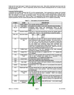
command phase is complete. (Please refer to Table 17 for the command set descriptions). These bytes of data must be
transferred in the order prescribed.
Before writing to the FDC, the host must examine the RQM and DIO bits of the Main Status Register. RQM and DIO
must be equal to "1" and "0" respectively before command bytes may be written. RQM is set false by the FDC after
each write cycle until the received byte is processed. The FDC asserts RQM again to request each parameter byte of
the command unless an illegal command condition is detected. After the last parameter byte is received, RQM remains
"0" and the FDC automatically enters the next phase as defined by the command definition.
The FIFO is disabled during the command phase to provide for the proper handling of the "Invalid Command" condition.
Execution Phase
All data transfers to or from the FDC occur during the execution phase, which can proceed in DMA mode as indicated in
the Specify command.
After a reset, the FIFO is disabled. Each data byte is transferred by a read/write or DMA cycle depending on the DMA
mode. The Configure command can enable the FIFO and set the FIFO threshold value.
The following paragraphs detail the operation of the FIFO flow control. In these descriptions, <threshold> is defined as
the number of bytes available to the FDC when service is requested from the host and ranges from 1 to 16. The
parameter FIFOTHR, which the user programs, is one less and ranges from 0 to 15.
A low threshold value (i.e. 2) results in longer periods of time between service requests, but requires faster servicing of
the request for both read and write cases. The host reads (writes) from (to) the FIFO until empty (full), then the transfer
request goes inactive. The host must be very responsive to the service request. This is the desired case for use with a
"fast" system.
A high value of threshold (i.e. 12) is used with a "sluggish" system by affording a long latency period after a service
request, but results in more frequent service requests.
Non-DMA Mode - Transfers from the FIFO to the Host
This part does not support non-DMA mode.
Non-DMA Mode - Transfers from the Host to the FIFO
This part does not support non-DMA mode.
DMA Mode - Transfers from the FIFO to the Host
The FDC generates a DMA request cycle when the FIFO contains (16 - <threshold>) bytes, or the last byte of a full
sector transfer has been placed in the FIFO. The DMA controller must respond to the request by reading data from the
FIFO. The FDC will deactivate the DMA request when the FIFO becomes empty by generating the proper sync for the
data transfer.
DMA Mode - Transfers from the Host to the FIFO
The FDC generates a DMA request cycle when entering the execution phase of the data transfer commands. The DMA
controller must respond by placing data in the FIFO. The DMA request remains active until the FIFO becomes full. The
DMA request cycle is reasserted when the FIFO has <threshold> bytes remaining in the FIFO. The FDC will terminate
the DMA cycle after a TC, indicating that no more data is required.
Data Transfer Termination
The FDC supports terminal count explicitly through the TC pin and implicitly through the underrun/overrun and end-of-
track (EOT) functions. For full sector transfers, the EOT parameter can define the last sector to be transferred in a
single or multi-sector transfer.
If the last sector to be transferred is a partial sector, the host can stop transferring the data in mid-sector, and the FDC
will continue to complete the sector as if a TC cycle was received. The only difference between these implicit functions
and TC cycle is that they return "abnormal termination" result status. Such status indications can be ignored if they were
expected.
Note that when the host is sending data to the FIFO of the FDC, the internal sector count will be complete when the FDC
reads the last byte from its side of the FIFO. There may be a delay in the removal of the transfer request signal of up to
the time taken for the FDC to read the last 16 bytes from the FIFO. The host must tolerate this delay.
Result Phase
The generation of the interrupt determines the beginning of the result phase. For each of the commands, a defined set
of result bytes has to be read from the FDC before the result phase is complete. These bytes of data must be read out
for another command to start.
SMSC DS – LPC47M14X
Page 40
Rev. 03/19/2001

 SMSC [ SMSC CORPORATION ]