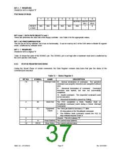
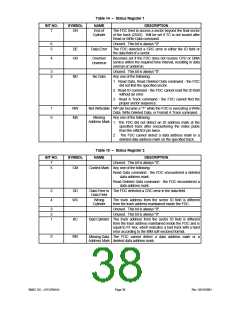
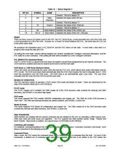
Table 16 – Status Register 3
NAME
BIT NO.
SYMBOL
DESCRIPTION
7
6
Unused. This bit is always "0".
WP
Write
Indicates the status of the WP pin.
Protected
5
4
3
Unused. This bit is always "1".
Indicates the status of the TRK0 pin.
Unused. This bit is always "1".
T0
Track 0
2
1,0
HD
DS1,0
Head Address Indicates the status of the HDSEL pin.
Drive Select Indicates the status of the DS1, DS0 pins.
RESET
There are three sources of system reset on the FDC: the PCI_RESET# pin, a reset generated via a bit in the DOR, and
a reset generated via a bit in the DSR. At power on, a Power On Reset initializes the FDC. All resets take the FDC out
of the power down state.
All operations are terminated upon a PCI_RESET#, and the FDC enters an idle state. A reset while a disk write is in
progress will corrupt the data and CRC.
On exiting the reset state, various internal registers are cleared, including the Configure command information, and the
FDC waits for a new command. Drive polling will start unless disabled by a new Configure command.
PCI_RESET# Pin (Hardware Reset)
The PCI_RESET# pin is a global reset and clears all registers except those programmed by the Specify command. The
DOR reset bit is enabled and must be cleared by the host to exit the reset state.
DOR Reset vs. DSR Reset (Software Reset)
These two resets are functionally the same. Both will reset the FDC core, which affects drive status information and the
FIFO circuits. The DSR reset clears itself automatically while the DOR reset requires the host to manually clear it. DOR
reset has precedence over the DSR reset. The DOR reset is set automatically upon a pin reset. The user must
manually clear this reset bit in the DOR to exit the reset state.
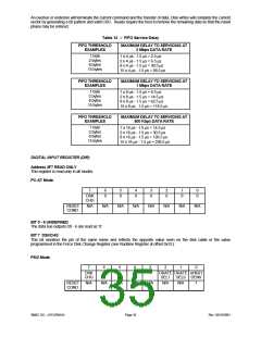
MODES OF OPERATION
The FDC has three modes of operation, PC/AT mode, PS/2 mode and Model 30 mode. These are determined by the
state of the Interface Mode bits in LD0-CRF0[3,2].
PC/AT mode
The PC/AT register set is enabled, the DMA enable bit of the DOR becomes valid (controls the interrupt and DMA
functions), and DENSEL is an active high signal.
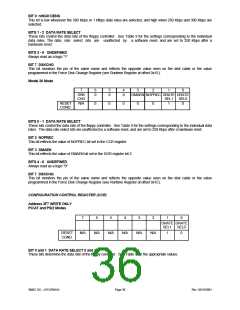
PS/2 mode
This mode supports the PS/2 models 50/60/80 configuration and register set. The DMA bit of the DOR becomes a
"don't care". The DMA and interrupt functions are always enabled, and DENSEL is active low.
Model 30 mode
This mode supports PS/2 Model 30 configuration and register set. The DMA enable bit of the DOR becomes valid
(controls the interrupt and DMA functions), and DENSEL is active low.
DMA TRANSFERS
DMA transfers are enabled with the Specify command and are initiated by the FDC by activating a DMA request cycle.
DMA read, write and verify cycles are supported. The FDC supports two DMA transfer modes: Single Transfer and
Burst Transfer. Burst mode is enabled via Logical Device 0-CRF0-Bit[1] (LD0-CRF0[1]).
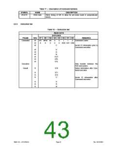
CONTROLLER PHASES
For simplicity, command handling in the FDC can be divided into three phases: Command, Execution, and Result. Each
phase is described in the following sections.
Command Phase
After a reset, the FDC enters the command phase and is ready to accept a command from the host. For each of the
commands, a defined set of command code bytes and parameter bytes has to be written to the FDC before the
SMSC DS – LPC47M14X
Page 39
Rev. 03/19/2001

 SMSC [ SMSC CORPORATION ]