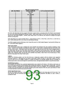
SER_IRQ Sampling Periods
SER_IRQ PERIOD
SIGNAL SAMPLED
Not Used
IRQ1
# OF CLOCKS PAST START
1
2
2
5
3
4
5
6
7
8
9
10
11
12
13
14
15
16
nIO_SMI/IRQ2
IRQ3
8
11
14
17
20
23
26
29
32
35
38
41
44
47
IRQ4
IRQ5
IRQ6
IRQ7
IRQ8
IRQ9
IRQ10
IRQ11
IRQ12
IRQ13
IRQ14
IRQ15
The SER_IRQ data frame will now support IRQ2 from a logical device, previously SER_IRQ Period 3 was reserved
for use by the System Management Interrupt (nSMI). When using Period 3 for IRQ2 the user should mask off the
SMI via the SMI Enable Register. Likewise, when using Period 3 for nSMI the user should not configure any logical
devices as using IRQ2.
SER_IRQ Period 14 is used to transfer IRQ13. Logical devices 0 (FDC), 3 (Par Port), 4 (Ser Port 1), 5 (Ser Port 2),
and 7 (KBD) shall have IRQ13 as a choice for their primary interrupt.
The SMI is enabled onto the SMI frame of the Serial IRQ via bit 6 of SMI Enable Register 2 and onto the SMI pin via
bit 7 of the SMI Enable Register 2.
Stop Cycle Control
Once all IRQ/Data Frames have completed the Host Controller will terminate SER_IRQ activity by initiating a Stop
Frame. Only the Host Controller can initiate the Stop Frame. A Stop Frame is indicated when the SER_IRQ is low
for two or three clocks. If the Stop Frame’s low time is two clocks then the next SER_IRQ Cycle’s sampled mode is
the Quiet mode; and any SER_IRQ device may initiate a Start Frame in the second clock or more after the rising
edge of the Stop Frame’s pulse. If the Stop Frame’s low time is three clocks then the next SER_IRQ Cycle’s sampled
mode is the Continuos mode; and only the Host Controller may initiate a Start Frame in the second clock or more
after the rising edge of the Stop Frame’s pulse.
Latency
Latency for IRQ/Data updates over the SER_IRQ bus in bridge-less systems with the minimum Host supported
IRQ/Data Frames of 17, will range up to 96 clocks (3.84μS with a 25MHz PCI Bus or 2.88uS with a 33MHz PCI Bus).
If one or more PCI to PCI Bridge is added to a system, the latency for IRQ/Data updates from the secondary or
tertiary buses will be a few clocks longer for synchronous buses, and approximately double for asynchronous buses.
EOI/ISR Read Latency
Any serialized IRQ scheme has a potential implementation issue related to IRQ latency. IRQ latency could cause an
EOI or ISR Read to precede an IRQ transition that it should have followed. This could cause a system fault. The host
interrupt controller is responsible for ensuring that these latency issues are mitigated. The recommended solution is
to delay EOIs and ISR Reads to the interrupt controller by the same amount as the SER_IRQ Cycle latency in order
to ensure that these events do not occur out of order.
AC/DC Specification Issue
All SER_IRQ agents must drive / sample SER_IRQ synchronously related to the rising edge of PCI bus clock. The
SER_IRQ pin uses the electrical specification of PCI bus. Electrical parameters will follow PCI spec. section 4,
sustained tri-state.
Page 93

 SMSC [ SMSC CORPORATION ]