been executed, MIRQ is controlled by P25, Writing a zero to P25 forces MIRQ low, a high forces MIRQ high. (MIRQ is
normally selected as IRQ12 for mouse support).
Gate A20
A general purpose P21 is used as a software controlled Gate A20 or user defined output.
8042 PINS
The 8042 functions P17, P16 and P12 are implemented as in a true 8042 part. Reference the 8042 spec for all timing.
A port signal of 0 drives the output to 0. A port signal of 1 causes the port enable signal to drive the output to 1 within 20-
30nsec. After 500nsec (six 8042 clocks) the port enable goes away and the external pull-up maintains the output signal
as 1.
In 8042 mode, the pins can be programmed as open drain. When programmed in open drain mode, the port enables
do not come into play. If the port signal is 0 the output will be 0. If the port signal is 1, the output tristates: an external
pull-up can pull the pin high, and the pin can be shared. In 8042 mode, the pins cannot be programmed as input nor
inverted through the GP configuration registers.
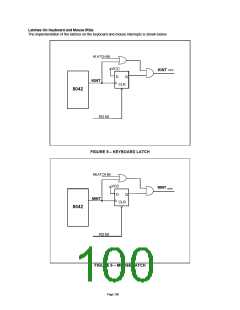
EXTERNAL KEYBOARD AND MOUSE INTERFACE
Industry-standard PC-AT-compatible keyboards employ a two-wire, bidirectional TTL interface for data transmission.
Several sources also supply PS/2 mouse products that employ the same type of interface. To facilitate system
expansion, the LPC47M10x provides four signal pins that may be used to implement this interface directly for an
external keyboard and mouse.
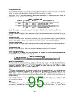
The LPC47M10x has four high-drive, open-drain output, bidirectional port pins that can be used for external serial
interfaces, such as external keyboard and PS/2-type mouse interfaces. They are KCLK, KDAT, MCLK, and MDAT. P26
is inverted and output as KCLK. The KCLK pin is connected to TEST0. P27 is inverted and output as KDAT. The
KDAT pin is connected to P10. P23 is inverted and output as MCLK. The MCLK pin is connected to TEST1. P22 is
inverted and output as MDAT. The MDAT pin is connected to P11. NOTE: External pull-ups may be required.
KEYBOARD POWER MANAGEMENT
The keyboard provides support for two power-saving modes: soft powerdown mode and hard powerdown mode. In soft
powerdown mode, the clock to the ALU is stopped but the timer/counter and interrupts are still active. In hard power
down mode the clock to the 8042 is stopped.
Soft Power Down Mode
This mode is entered by executing a HALT instruction. The execution of program code is halted until either RESET is
driven active or a data byte is written to the DBBIN register by a master CPU. If this mode is exited using the interrupt,
and the IBF interrupt is enabled, then program execution resumes with a CALL to the interrupt routine, otherwise the
next instruction is executed. If it is exited using RESET then a normal reset sequence is initiated and program execution
starts from program memory location 0.
Hard Power Down Mode
This mode is entered by executing a STOP instruction. The oscillator is stopped by disabling the oscillator driver
cell. When either RESET is driven active or a data byte is written to the DBBIN register by a master CPU, this mode will
be exited (as above). However, as the oscillator cell will require an initialization time, either RESET must be held active
for sufficient time to allow the oscillator to stabilize. Program execution will resume as above.
INTERRUPTS
The LPC47M10x provides the two 8042 interrupts: IBF and the Timer/Counter Overflow.
MEMORY CONFIGURATIONS
The LPC47M10x provides 2K of on-chip ROM and 256 bytes of on-chip RAM.
Register Definitions
Host I/F Data Register
The Input Data register and Output Data register are each 8 bits wide. A write to this 8 bit register will load the Keyboard
Data Read Buffer, set the OBF flag and set the KIRQ output if enabled. A read of this register will read the data from the
Keyboard Data or Command Write Buffer and clear the IBF flag. Refer to the KIRQ and Status register descriptions for
more information.
Page 96

 SMSC [ SMSC CORPORATION ]