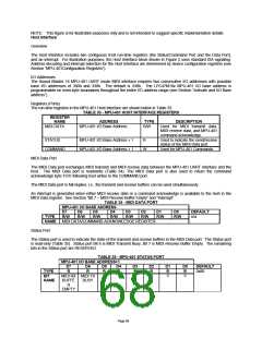
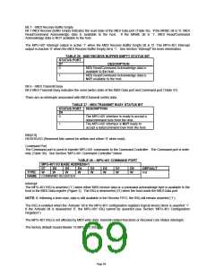
NOTE: The command acknowledge byte will appear as the next available data byte in the receive buffer of the MIDI
Data port. For example if the receive FIFO is not empty when an MPU-401 RESET command is received, the
command acknowledge will appear first, before any unread FIFO data. In the examples above, the receive FIFO is
cleared before the command acknowledge byte is placed in the MIDI Data port read buffer.
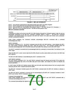
MIDI UART
Overview
The UART is used to transmit and receive MIDI protocol data from the MIDI Data port in the Host Interface (see
Section “Host Interface”).
The MIDI protocol requires 31.25k Baud (±1%) and 10 bits total per frame: 1 start bit, 8 data bits, no parity, and 1
stop bit. For example, there are 320 microseconds per serial MIDI data byte. MIDI data is transferred LSB first
(Figure 4).
The UART is configured in full-duplex mode for the MPU-401 MIDI Interface, with 16-byte send/receive FIFOs.
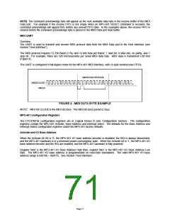
MIDI RX DATA BYTE (01H)
MIDI RX CLOCK1
MIDI_IN
FIGURE 4 - MIDI DATA BYTE EXAMPLE
NOTE1 MIDI RX CLOCK is the MIDI bit clock. The MIDI bit clock period is 32μs.
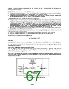
MPU-401 Configuration Registers
The LPC47M10x configuration registers are in Logical Device B (see Configuration section). The configuration
registers contain the MPU-401 Activate, Base Address and Interrupt select. The defaults for the Base Address and
Interrupt Select configuration registers match the MPU-401 factory defaults.
Activate and I/O Base Address
When the Activate bit D0 is ‘0’, the MPU-401 I/O base address decoder is disabled, the IRQ is always deasserted,
and the MPU-401 hardware is in a minimum power-consumption state. When the Activate bit is ‘1’, the MPU-401 I/O
base address decoder and the IRQ are enabled, and the MPU-401 hardware is fully powered.
Register 0x60 is the MPU-401 I/O Base Address High Byte, register 0x61 is the MPU-401 I/O Base Address Low
Byte. The MPU-401 I/O base address is programmable on even-byte boundaries. The valid MPU-401 I/O base
address range is 0x0100 – 0x0FFE. See Section “Host Interface”.
Page 71

 SMSC [ SMSC CORPORATION ]