DATA TRANSFER COMMANDS
All of the Read Data, Write Data and Verify type commands use the same parameter bytes and return the same results
information, the only difference being the coding of bits 0-4 in the first byte.
An implied seek will be executed if the feature was enabled by the Configure command. This seek is completely
transparent to the user. The Drive Busy bit for the drive will go active in the Main Status Register during the seek portion
of the command. If the seek portion fails, it is reflected in the results status normally returned for a Read/Write Data
command. Status Register 0 (ST0) would contain the error code and C would contain the cylinder on which the seek
failed.
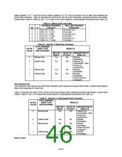
Read Data
A set of nine (9) bytes is required to place the FDC in the Read Data Mode. After the Read Data command has been
issued, the FDC loads the head (if it is in the unloaded state), waits the specified head settling time (defined in the
Specify command), and begins reading ID Address Marks and ID fields. When the sector address read off the diskette
matches with the sector address specified in the command, the FDC reads the sector's data field and transfers the data
to the FIFO.
After completion of the read operation from the current sector, the sector address is incremented by one and the data
from the next logical sector is read and output via the FIFO. This continuous read function is called "Multi-Sector Read
Operation". Upon receipt of the TC cycle, or an implied TC (FIFO overrun/underrun), the FDC stops sending data but
will continue to read data from the current sector, check the CRC bytes, and at the end of the sector, terminate the Read
Data Command.
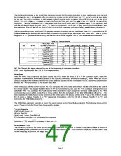
N determines the number of bytes per sector (see Table 18). If N is set to zero, the sector size is set to 128. The DTL
value determines the number of bytes to be transferred. If DTL is less than 128, the FDC transfers the specified number
of bytes to the host. For reads, it continues to read the entire 128-byte sector and checks for CRC errors. For writes, it
completes the 128-byte sector by filling in zeros. If N is not set to 00 Hex, DTL should be set to FF Hex and has no
impact on the number of bytes transferred.
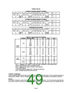
Table 18 - Sector Sizes
N
00
01
02
03
..
SECTOR SIZE
128 bytes
256 bytes
512 bytes
1024 bytes
...
07
16 Kbytes
The amount of data which can be handled with a single command to the FDC depends upon MT (multi-track) and N
(number of bytes/sector).
The Multi-Track function (MT) allows the FDC to read data from both sides of the diskette. For a particular cylinder, data
will be transferred starting at Sector 1, Side 0 and completing the last sector of the same track at Side 1.
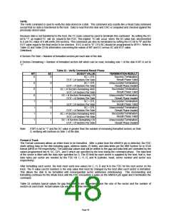
If the host terminates a read or write operation in the FDC, the ID information in the result phase is dependent upon the
state of the MT bit and EOT byte. Refer to Table 19.
At the completion of the Read Data command, the head is not unloaded until after the Head Unload Time Interval
(specified in the Specify command) has elapsed. If the host issues another command before the head unloads, then
the head settling time may be saved between subsequent reads.
If the FDC detects a pulse on the nINDEX pin twice without finding the specified sector (meaning that the diskette's
index hole passes through index detect logic in the drive twice), the FDC sets the IC code in Status Register 0 to "01"
indicating abnormal termination, sets the ND bit in Status Register 1 to "1" indicating a sector not found, and terminates
the Read Data Command.
After reading the ID and Data Fields in each sector, the FDC checks the CRC bytes. If a CRC error occurs in the ID or
data field, the FDC sets the IC code in Status Register 0 to "01" indicating abnormal termination, sets the DE bit flag in
Page 45

 SMSC [ SMSC CORPORATION ]