Three Port 10/100 Managed Ethernet Switch with MII
Datasheet
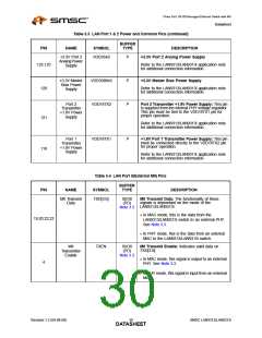
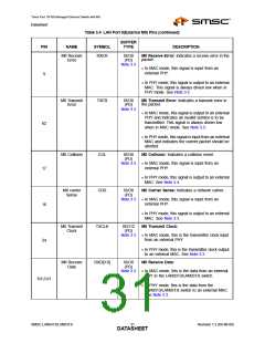
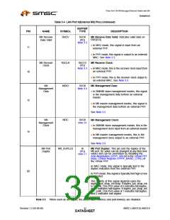
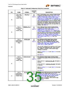
Table 3.4 LAN Port 0(External MII) Pins (continued)
BUFFER
TYPE
PIN
NAME
SYMBOL
DESCRIPTION
MII Receive
Error
RXER
IS/O8
(PD)
Note 3.3
MII Receive Error: Indicates a receive error in the
packet.
In MAC mode, this signal is input from an
external PHY.
9
In PHY mode, this signal is output to an external
MAC. This signal is always driven low when in
PHY mode. See Note 3.3.
MII Transmit
Error
TXER
IS/O8
(PD)
Note 3.3
MII Transmit Error: Indicates a transmit error in
the packet.
In MAC mode, this signal is output to an external
PHY and indicates an invalid symbol is to be
transmitted. This signal is always driven low
when in MAC mode. See Note 3.3.
62
In PHY mode, this signal is input from an external
MAC and indicates the current packet should be
aborted.
MII Collision
COL
CRS
IS/O8
(PU)
MII Collision: Indicates a collision event.
Note 3.4 In MAC mode, this signal is input from an
external PHY.
17
16
24
In PHY mode, this signal is output to an external
MAC. See Note 3.4.
MII carrier
Sense
IS/O8
(PD)
MII Carrier Sense: Indicates a network carrier.
Note 3.3 In MAC mode, this signal is input from an
external PHY.
In PHY mode, this signal is output to an external
MAC. See Note 3.3.
MII Transmit
Clock
TXCLK
IS/O12
(PD)
MII Transmit Clock:
Note 3.3 In MAC mode, this is the transmitter clock input
from an external PHY.
In PHY mode, this is the transmitter clock output
to an external MAC. See Note 3.3.
MII Receive
Data
RXD[3:0]
IS/O8
(PD)
MII Receive Data:
Note 3.3 In MAC mode, this is the data from an external
PHY to the LAN9313/LAN9313i switch.
8,6,5,61
In PHY mode, this is the data from the
LAN9313/LAN9313i switch to an external MAC.
See Note 3.3.
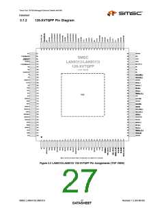
SMSC LAN9313/LAN9313i
Revision 1.2 (04-08-08)
DATA3S1HEET

 SMSC [ SMSC CORPORATION ]