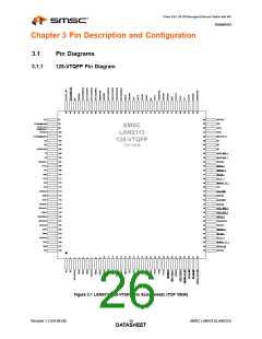
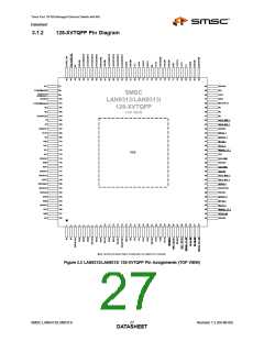
Three Port 10/100 Managed Ethernet Switch with MII
Datasheet
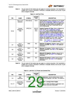
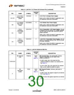
Table 3.3 LAN Port 1 & 2 Power and Common Pins (continued)
BUFFER
TYPE
PIN
NAME
SYMBOL
DESCRIPTION
+3.3V Port 2
AnalogPower
Supply
VDD33A2
P
P
P
+3.3V Port 2 Analog Power Supply
122,125
Refer to the LAN9313/LAN9313i application note
for additional connection information.
+3.3V Master
Bias Power
Supply
VDD33BIAS
VDD18TX2
+3.3V Master Bias Power Supply
120
121
Refer to the LAN9313/LAN9313i application note
for additional connection information.
Port 2
Transmitter
+1.8V Power
Supply
Port 2 Transmitter +1.8V Power Supply: This pin
is supplied from the internal PHY voltage regulator.
This pin must be tied to the VDD18TX1 pin for
proper operation.
Refer to the LAN9313/LAN9313i application note
for additional connection information.
Port 1
Transmitter
+1.8V Power
Supply
VDD18TX1
P
+1.8V Port 1 Transmitter Power Supply: This pin
must be connected directly to the VDD18TX2 pin
for proper operation.
118
Refer to the LAN9313/LAN9313i application note
for additional connection information.
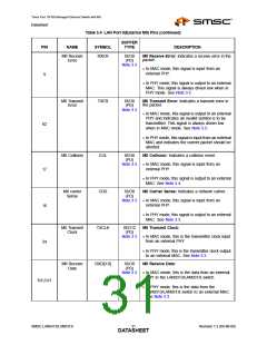
Table 3.4 LAN Port 0(External MII) Pins
BUFFER
PIN
NAME
SYMBOL
TYPE
DESCRIPTION
MII Transmit
Data
TXD[3:0]
IS/O8
(PD)
Note 3.3
MII Transmit Data: The functionality of these
signals is dependant on the mode of the
LAN9313/LAN9313i:
In MAC mode, this is the data from the
LAN9313/LAN9313i switch to an external PHY.
See Note 3.3.
19,20,22,23
In PHY mode, this is the data from an external
MAC to the LAN9313/LAN9313i switch.
MII
Transmitter
Enable
TXEN
IS/O8
(PD)
Note 3.3
MII Transmit Enable: Indicates valid data on
TXD[3:0].
In MAC mode, this signal is output to an external
4
PHY. See Note 3.3.
In PHY mode, this signal is input from an external
MAC.
Revision 1.2 (04-08-08)
SMSC LAN9313/LAN9313i
DATA3S0HEET

 SMSC [ SMSC CORPORATION ]