Three Port 10/100 Managed Ethernet Switch with MII
Datasheet
3.2
Pin Descriptions
This section contains the descriptions of the LAN9313/LAN9313i pins. The pin descriptions have been
broken into functional groups as follows:
LAN Port 1 Pins
LAN Port 2 Pins
LAN Port 1 & 2 Power and Common Pins
LAN Port 0(External MII) Pins
Dedicated Configuration Strap Pins
EEPROM Pins
Serial Management Pins
Miscellaneous Pins
PLL Pins
Core and I/O Power and Ground Pins
No-Connect Pins
Note: A list of buffer type definitions is provided in Section 1.2, "Buffer Types," on page 16.
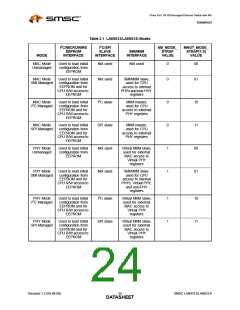
Table 3.1 LAN Port 1 Pins
BUFFER
TYPE
PIN
NAME
SYMBOL
DESCRIPTION
Port 1 LED
Indicators
nP1LED[3:0]
OD12
LED Indicators: When configured as LED outputs
via the LED Configuration Register (LED_CFG),
these pins are open-drain, active low outputs and
the pull-ups and input buffers are disabled. The
functionality of each pin is determined via the
LED_CFG[9:8] bits.
General
Purpose I/O
Data
GPIO[3:0]
IS/O12/
OD12
(PU)
General Purpose I/O Data: When configured as
GPIO via the LED Configuration Register
(LED_CFG), these general purpose signals are
fully programmable as either push-pull outputs,
open-drain outputs or Schmitt-triggered inputs by
writing the General Purpose I/O Configuration
Register (GPIO_CFG) and General Purpose I/O
Data & Direction Register (GPIO_DATA_DIR). The
pull-ups are enabled in GPIO mode. The input
buffers are disabled when set as an output.
89-92
Note:
See Chapter 12, "GPIO/LED Controller,"
on page 142 for additional details.
Port 1
Ethernet TX
Negative
TXN1
TXP1
RXN1
RXP1
AIO
AIO
AIO
AIO
Ethernet TX Negative: Negative output of Port 1
Ethernet transmitter. See Note 3.1 for additional
information.
110
111
115
116
Port 1
Ethernet TX
Positive
Ethernet TX Positive: Positive output of Port 1
Ethernet transmitter. See Note 3.1 for additional
information.
Port 1
Ethernet RX
Negative
Ethernet RX Negative: Negative input of Port 1
Ethernet receiver. See Note 3.1 for additional
information.
Port 1
Ethernet RX
Positive
Ethernet RX Positive: Positive input of Port 1
Ethernet receiver. See Note 3.1 for additional
information.
Revision 1.2 (04-08-08)
SMSC LAN9313/LAN9313i
DATA2S8HEET

 SMSC [ SMSC CORPORATION ]