Once a Start Frame has been initiated, the host controller will take over driving the IRQSER low in the next clock and
will continue driving the IRQSER low for a programmable period of three to seven clocks. This makes a total low
pulse width of four to eight clocks. Finally, the host controller will drive the IRQSER back high for one clock, then tri-
state.
Any IRQSER device (e.g., The FDC37N3869) which detects any transition on an IRQ/Data line for which it is
responsible must initiate a Start Frame in order to update the host controller unless the IRQSER is already in an
IRQSER Cycle and the IRQ/Data transition can be delivered in that IRQSER Cycle.
Continuous (Idle) Mode
In Continuous Mode only the host controller can initiate a Start Frame to update IRQ/Data line information. All other
IRQSER agents become passive and may not initiate a Start Frame. IRQSER Start Frame will be driven low for four
to eight clocks by the Host Controller.
Continuous Mode has serves two purposes: it can be used to stop or idle the IRQSER, or the host controller can
operate IRQSER continuously by initiating a Start Frame at the end of every Stop Frame.
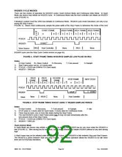
IRQSER IRQ/DATA FRAMES
Once a Start Frame has been initiated, the FDC37N3869 will watch for the rising edge of the Start Pulse and start
counting IRQ/Data Frames.
Each IRQ/Data Frame has three phases. Each phase takes one PCI clock: Sample phase, Recovery phase, and
Turn-around phase. During the Sample phase the FDC37N3869 must drive the IRQSER (SIRQ pin) low if and only if
the last detected IRQ/Data value was low. If the last detected IRQ/Data value was high IRQSER must be left tri-
stated.
During the Recovery phase the FDC37N3869 must drive the SIRQ high if and only if it had driven the IRQSER low
during the previous Sample Phase. During the Turn-around Phase the FDC37N3869 must tri-state SIRQ.
The FDC37N3869 will drive the IRQSER line low at the appropriate sample point if its associated IRQ/Data line is low,
regardless of which device initiated the Start Frame.
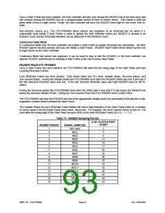
The Sample Phase for each IRQ/Data Frame follows the low to high transition of the Start Frame pulse by a number
of clocks equal to the IRQ/Data Frame times three, minus one. For example, the IRQ5 Sample Phase occurs on 17th
clock after the rising edge of the Start Pulse because IRQ5 is the sixth IRQ/Data Frame ((6 x 3) - 1 = 17).
Table 73 - IRQSER Sampling Periods
# OF CLOCKS PAST
START
2
IRQSER PERIOD
SIGNAL SAMPLED
Not Used
IRQ1
1
2
5
3
IRQ2
8
4
5
6
7
8
9
10
11
12
13
14
15
16
IRQ3
IRQ4
IRQ5
IRQ6
IRQ7
IRQ8
IRQ9
IRQ10
IRQ11
IRQ12
IRQ13
IRQ14
IRQ15
11
14
17
20
23
26
29
32
35
38
41
44
47
SMSC DS – FDC37N3869
Page 93
Rev. 10/25/2000

 SMSC [ SMSC CORPORATION ]