The IRQSER IRQ/Data Frame will supports IRQ2 from a logical device. Previously, IRQSER Period 3 was reserved
for use by the System Management Interrupt (nSMI). When using Period 3 for IRQ2 the user should mask off the
SMI via the SMI Enable Register. Likewise, when using Period 3 for nSMI the user should not configure any logical
devices as using IRQ2. Note: There is no SMI support in the FDC37N3869.
STOP CYCLE CONTROL
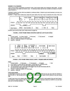
Once all IRQ/Data Frames have completed, the host controller will terminate IRQSER activity by initiating a Stop
Frame. Only the host controller can initiate the Stop Frame.
A Stop Frame is indicated when the IRQSER is low for two or three clocks. If the Stop Frame is low for two clocks the
next IRQSER Cycle operates in the Quiet mode and any IRQSER device may initiate a Start Frame in the second
clock or more after the rising edge of the Stop Frame pulse. If the Stop Frame is low for three clocks the next
IRQSER Cycle operates in Continuous mode and only the host controller may initiate a Start Frame in the second
clock or more after the rising edge of the Stop Frame pulse.
LATENCY
Latency for IRQ/Data updates over the IRQSER bus in bridge-less systems with the minimum IRQ/Data Frames of
seventeen will range up to 96 clocks (3.84uS with a 25MHz PCI Bus or 2.88uS with a 33MHz PCI Bus).
If one or more PCI to PCI Bridges are added to a system, the latency for IRQ/Data updates from the secondary or
tertiary buses will be a few clocks longer for synchronous buses, and approximately double for asynchronous buses.
EOI/ISR READ LATENCY
Any serialized IRQ scheme has a potential implementation issue related to IRQ latency. IRQ latency could cause an
EOI or ISR Read to precede an IRQ transition that it should have followed. This could cause a system fault.
The host controller is responsible for ensuring that these latency issues are mitigated. The recommended solution is
to delay EOIs and ISR Reads to the interrupt controller by the same amount as the IRQSER Cycle latency in order to
ensure that these events do not occur out of order.
AC/DC SPECIFICATION ISSUE
All IRQSER agents must drive/sample IRQSER synchronously relative to the rising edge of the PCI bus clock. The
IRQSER (SIRQ) pin uses the electrical specification of PCI bus.
RESET AND INITIALIZATION
The IRQSER bus uses RESET_DRV as its reset signal. The IRQSER pin is tri-stated by all agents while
RESET_DRV is active. Following reset, IRQSER Slaves are put into Continuous (IDLE) mode. The host controller is
responsible for starting the initial IRQSER cycle to collect the system’s IRQ/Data default values.
The system then follows with the Continuous/Quiet mode protocol as determined by the Stop Frame pulse width for
subsequent IRQSER Cycles. It is the responsibility of the host controller to provide the default values to 8259’s and
other system logic before the first IRQSER Cycle is performed.
For IRQSER system suspend, insertion, or removal application, the host controller should be programmed in
Continuous (IDLE) mode first. This is to guarantee that the IRQSER bus is in the IDLE state before the system
configuration changes.
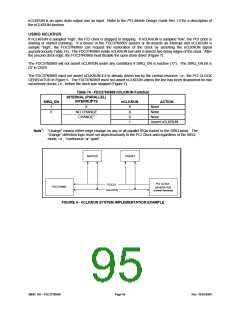
Add PCI nCLKRUN Support
OVERVIEW
The FDC37N3869 supports the PCI nCLKRUN signal. nCLKRUN is used to indicate the PCI clock status as well as
to request that a stopped clock be started. See Figure 6 for an example of a typical system implementation using
nCLKRUN.
nCLKRUN support is required because the FDC37N3869 interrupt interface relies entirely on Serial IRQs. If an SIO
interrupt occurs while the PCI clock is stopped, nCLKRUN must be asserted before the interrupt can be serviced.
If the FDC37N3869 SIRQ_EN signal is inactive, nCLKRUN support is also disabled. The FDC37N3869 nCLKRUN
signal is multiplexed with nADRx on TQFP pin number 92. See Configuration Register CR03 for a description of the
TQFP pin 92 multiplex controls.
SMSC DS – FDC37N3869
Page 94
Rev. 10/25/2000

 SMSC [ SMSC CORPORATION ]