UART Power Management
Direct UART power management is controlled by the UART1 and UART2 Power Down bits in Configuration Register
2. Refer to section CR02 on page 100 for more information.
UART Auto Power Management is enabled by the UART 1 and UART 2 Enable bits in Configuration Register 7 (see
section CR07on page 103). When set, these bits enable the following auto power management features:
1)
2)
The transmitter enters auto powerdown when the transmit buffer and transmit shift register are empty.
The receiver enters powerdown when the following conditions are all met:
ꢀ
ꢀ
Receive FIFO is empty
The receiver is waiting for a start bit.
Note: While in the powerdown state, the Ring Indicator interrupts are still valid and are activated when the RI
inputs change.
The UART transmitters exit the powerdown state on a write to the XMIT buffer. The UART receivers exit the auto
powerdown state when RXDx changes state.
Parallel Port
Direct parallel port power management is controlled by the Parallel Port Power bit in Configuration Register 1. Refer
to section CR01 on page 99 for more information.
Parallel port Auto Power Management is enabled by the Parallel Port Enable bit in Configuration Register 7 (see
section CR07 on page 103). When set, this bit allows the ECP or EPP logical parallel port blocks to be placed into
the powerdown state as follows:
The EPP logic is in powerdown under any of the following conditions:
1)
2)
EPP is not enabled in the configuration registers.
EPP is not selected through ecr while in ECP mode.
The ECP logic is in powerdown under any of the following conditions:
1)
2)
ECP is not enabled in the configuration registers.
SPP, PS/2 Parallel port or EPP mode is selected through ecr while in ECP mode.
The parallel port logic can change powerdown modes when the ECP mode is changed through the ecr register or
when the parallel port mode is changed through the configuration registers.
Serial IRQ
INTRODUCTION
The FDC37N3869 provides a serial interrupt interface to the host. This scheme adheres to the Serial IRQ
Specification for PCI Systems, Version 6.0. The CLK33, SIRQ, and nCLKRUN pins are required for this interface.
The Serial IRQ Enable bit D7 in CR29 activates the serial interrupt interface.
The IRQ/Data serializer is a Wired-OR structure that simply passes the state of one or more device IRQs and/or Data
to the Host Controller. The transfer can be initiated by either a device or the Host. Both high and low transitions are
reported in this protocol.
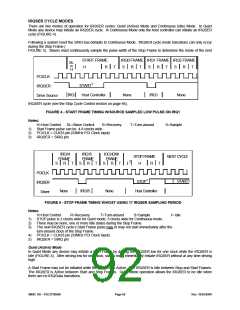
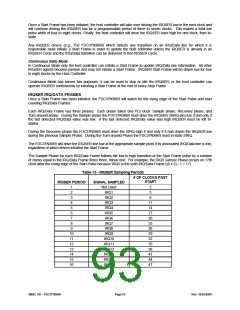
A transfer, called an IRQSER Cycle, consists of three frame types:
1)
2)
3)
One START Frame
One or more IRQ/DATA Frames
One STOP Frame
The Serial IRQ protocol uses the PCI Clock as its clock source. The PCI clock conforms to the PCI bus electrical
specification.
SMSC DS – FDC37N3869
Page 91
Rev. 10/25/2000

 SMSC [ SMSC CORPORATION ]