Power management is provided for the following FDC37N3869 logical devices: Floppy Disk, UART1, UART2 and the
Parallel Port. For each logical device two types of power management are provided; direct powerdown and auto
powerdown.
Direct powerdown is controlled by the powerdown bits in the configuration registers. One bit is provided for each
logical device. Auto powerdown can be enabled for each logical device by setting the Auto Powerdown Enable bits in
the configuration registers. In addition, a chip-level hardware powerdown function has been provided through the
PWRGD pin. Refer to Table 1 and to other descriptions of the PWRGD function, for example section
CONFIGURATION, for more information.
FDC Power Management
Direct FDC power management is controlled by FDC Power (bit 3) of Configuration Register 0 (see section CR00 on
page 99). FDC auto power management is enabled by Floppy Disk Enable (bit 7) in CR7 (see section CR07 on
page 103). An internal timer is activated as soon as auto power management is enabled. During the timer
countdown any operation involving the MSR or the Data Register (FIFO) will re-initialize the timer. In auto powerdown
mode the FDC enters the powerdown state when all of the following conditions have been met:
1)
2)
The motor enable pins of the DOR register are inactive (zero).
The FDC is idle; MSR=80H and INT = 0 (INT may be high even if MSR = 80H due to polling
interrupts).
3)
4)
The internal head unload timer has expired.
The 10msec auto powerdown timer has lapsed.
Disabling the FDC auto power management cancels the internal timer and prevents any of the above conditions from
re-enabling the powerdown state.
Note: At least 8us delay should be added when exiting FDC Auto Powerdown mode. If the operating
environment is such that this delay cannot be guaranteed, the auto powerdown mode should not be used
and Direct powerdown mode should be used instead. The Direct powerdown mode requires at least 8us
delay at 250K bits/sec configuration and 4us delay at 500K bits/sec. The delay should be added so that the
internal microcontroller can prepare itself to accept commands.
DSR FROM POWERDOWN
If DSR powerdown is used when the part is in auto powerdown, the DSR powerdown will override the auto
powerdown. However, when the part is awakened from DSR powerdown, the auto powerdown will once again
become effective.
WAKE UP FROM AUTO POWERDOWN
If the FDC enters the powerdown state through the auto powerdown mode, wake up will occur after a reset or by
access to the specific registers shown below. If a hardware or software reset is used the part will follow the normal
reset sequence. If wake up occurs as a result of access through selected registers the FDC37N3869 will resume
normal operation as if the FDC had never powered-down.
The following register accesses will wake up the FDC:
1)
Enabling any one of the motor enable bits in the DOR register (reading the DOR does not awaken the
part).
2)
3)
A read from the MSR register.
A read or write to the Data register.
Once awake, the FDC37N3869 will reinitiate the auto powerdown timer for 10ms. The FDC will powerdown again
when all of the powerdown conditions are met.
REGISTER BEHAVIOR
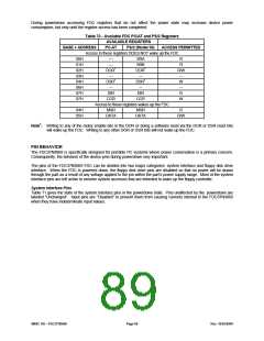
Table 70 reiterates the available FDC PC/AT and PS/2, including Model 30 mode, registers. In order to maintain
software transparency, access to all the registers must be maintained regardless of the power state. As Table 70
shows, two kinds of registers are identified based on whether access results in the FDC remaining in the powerdown
state or not.
Registers that will not awaken the FDC can be accessed during powerdown without changing the powerdown state
but will reflect the true register status as shown in the FDC register description. For example, a write to one of these
registers will result in the FDC retaining the data and subsequently using it appropriately when the block reawakens.
SMSC DS – FDC37N3869
Page 88
Rev. 10/25/2000

 SMSC [ SMSC CORPORATION ]