Hardware Interface
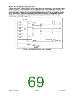
The FDC37N3869 IR hardware interface is shown in Figure 3. This interface supports two types of external FIR
transceiver modules. One uses a mode pin (IR Mode) to program the data rate, while the other has a second Rx data
pin (IRR3). The FDC37N3869 uses Pin 21 for these functions. Pin 21 has IR Mode and IRR3 as its first and second
alternate function, respectively. These functions are selected through CR29 as shown in
Table 57.
Table 57 - FIR Transceiver Module-Type Select
HP MODE1
FUNCTION
0
1
IR Mode
IRR3
Note1: HPMODE is CR29, BIT 4 (see section CR29 on page 112). Refer to the Infrared Interface Block Diagram on
the following page for HPMODE implementation.
The FAST bit is used to select between the SIR mode and FIR mode receiver, regardless of the transceiver type. If
FAST = 1, the FIR mode receiver is selected; if FAST = 0, the SIR mode receiver is selected (Table 58).
Table 58 - IR Rx Data Pin Selection
CONTROL SIGNALS
INPUTS
FAST
HPMODE
RX1
RX1=RXD2
RX1=RXD2
RX2
0
X
1
X
0
1
RX2=IRRX2
RX2=IRRX2
RX2=IR Mode/IRR3
RX1=IR Mode/IRR3
SMSC DS – FDC37N3869
Page 68
Rev. 10/25/2000

 SMSC [ SMSC CORPORATION ]