Notes On Serial Port FIFO Mode Operation
GENERAL
The RCVR FIFO will hold up to 16 bytes regardless of which trigger level is selected.
TX AND RX FIFO OPERATION
The Tx portion of the UART transmits data through TXD as soon as the CPU loads a byte into the Tx FIFO. The
UART will prevent loads to the Tx FIFO if it currently holds 16 characters. Loading to the Tx FIFO will again be
enabled as soon as the next character is transferred to the Tx shift register. These capabilities account for the largely
autonomous operation of the Tx.
The UART starts the above operations typically with a Tx interrupt. The chip issues a Tx interrupt whenever the Tx
FIFO is empty and the Tx interrupt is enabled, except in the following instance. Assume that the Tx FIFO is empty
and the CPU starts to load it. When the first byte enters the FIFO the Tx FIFO empty interrupt will transition from
active to inactive. Depending on the execution speed of the service routine software, the UART may be able to
transfer this byte from the FIFO to the shift register before the CPU loads another byte. If this happens, the Tx FIFO
will be empty again and typically the UART’s interrupt line would transition to the active state. This could cause a
system with an interrupt control unit to record a Tx FIFO empty condition, even though the CPU is currently servicing
that interrupt. Therefore, after the first byte has been loaded into the FIFO the UART will wait one serial character
transmission time before issuing a new Tx FIFO empty interrupt.
This one character Tx interrupt delay will remain active until at least two bytes have been loaded into the FIFO,
concurrently. When the Tx FIFO empties after this condition, the Tx interrupt will be activated without a one character
delay.
Rx support functions and operation are quite different from those described for the transmitter. The Rx FIFO receives
data until the number of bytes in the FIFO equals the selected interrupt trigger level. At that time if Rx interrupts are
enabled, the UART will issue an interrupt to the CPU. The Rx FIFO will continue to store bytes until it holds 16 of
them. It will not accept any more data when it is full. Any more data entering the Rx shift register will set the Overrun
Error flag. Normally, the FIFO depth and the programmable trigger levels will give the CPU ample time to empty the
Rx FIFO before an overrun occurs.
One side-effect of having a Rx FIFO is that the selected interrupt trigger level may be above the data level in the
FIFO. This could occur when data at the end of the block contains fewer bytes than the trigger level. No interrupt
would be issued to the CPU and the data would remain in the UART. To prevent the software from having to check
for this situation the chip incorporates a time-out interrupt.
The time-out interrupt is activated when there is a least one byte in the Rx FIFO, and neither the CPU nor the Rx shift
register has accessed the Rx FIFO within 4 character times of the last byte. The time-out interrupt is cleared or reset
when the CPU reads the Rx FIFO or another character enters it.
These FIFO related features allow optimization of CPU/UART transactions and are especially useful given the higher
baud rate capability (256K baud).
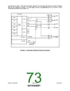
INFRARED INTERFACE
The FDC37N769 infrared interface provides a two-way wireless communications port using infrared as the
transmission medium. Several infrared protocols have been provided in this implementation including IrDA v1.1
(SIR/FIR), ASKIR, and Consumer IR (
FIGURE 3). For more information consult the SMSC Infrared Communication Controller (IRCC) specification.
The IrDA v1.0 (SIR) and ASKIR formats are driven by the ACE registers found in UART2. The UART2 registers are
described in section
SERIAL PORT (UART) starting on page 58. The base address for UART2 is programmed in CR25, the UART2 Base
Address Register (see section
CR25 on page 109).
SMSC DS – FDC37N769
Page 71 of 137
Rev. 02-16-07
DATASHEET

 SMSC [ SMSC CORPORATION ]