Interrupt Pending, Bit 0
The Interrupt Pending bit can be used in either a hardwired prioritized or polled environment to indicate whether an
interrupt is pending. When bit 0 is a logic “0”, an interrupt is pending and the contents of the IIR may be used as a
pointer to the appropriate internal service routine. When bit 0 is a logic “1”, no interrupt is pending.
Interrupt ID, Bits 1 - 2
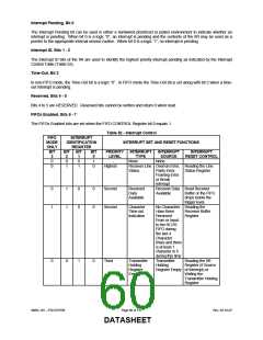
The Interrupt ID bits of the IIR are used to identify the highest priority interrupt pending as indicated by the Interrupt
Control Table (Table 52).
Time-Out, Bit 3
In non-FIFO mode, the Time-Out bit is a logic “0”. In FIFO mode the Time-Out bit is set along with bit 2 when a time-
out interrupt is pending.
Reserved, Bits 4 - 5
Bits 4 to 5 are RESERVED. Reserved bits cannot be written and return 0 when read.
FIFOs Enabled, Bits 6 - 7
The FIFOs Enabled bits are set when the FIFO CONTROL Register bit 0 equals 1.
Table 52 - Interrupt Control
FIFO
MODE
ONLY
BIT
3
INTERRUPT
IDENTIFICATION
REGISTER
INTERRUPT SET AND RESET FUNCTIONS
BIT
2
BIT
1
BIT
0
PRIORITY
LEVEL
-
INTERRUPT
TYPE
None
INTERRUPT
SOURCE
None
INTERRUPT
RESET CONTROL
0
0
0
1
-
0
1
1
0
Highest
Receiver Line Overrun Error, Reading the Line
Status
Parity Error,
Framing Error
or Break
Status Register
Interrupt
0
1
1
1
0
0
0
0
Second
Second
Received
Data
Available
Receiver Data Read Receiver
Available
Buffer or the FIFO
drops below the
trigger level.
Character
Time-out
Indication
No Characters Reading the
Have Been
Removed
Receiver Buffer
Register
From or Input
to the RCVR
FIFO during
the last 4
Character
times and there
is at least 1
character in it
during this time
Transmitter
Holding
0
0
1
0
Third
Transmitter
Holding
Reading the IIR
Register (if Source
Register
Empty
Register Empty of Interrupt) or
Writing the
Transmitter Holding
Register
SMSC DS – FDC37N769
Page 60 of 137
Rev. 02-16-07
DATASHEET

 SMSC [ SMSC CORPORATION ]