Fan Control Device with Hardware Monitoring and Acoustic Noise Reduction Features
Datasheet
b. Status bits may be set.
c. Setting the START bit to 1 does not prevent the limit and parameter registers from being written.
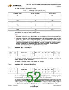
Note: Once programmed, the register values will be saved when start bit is reset to ‘0’.
7.2.10
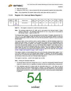
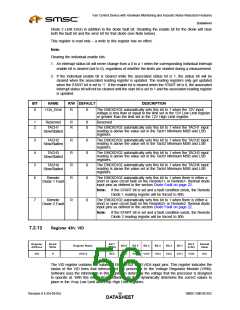
Register 41h: Interrupt Status Register 1
Register
Address
Read/
Write
Bit 7
Bit 0
Default
Value
Register Name
Bit 6
Bit 5
Bit 4
Bit 3
Bit 2
Bit 1
(MSb)
(LSb)
41h
R-C
(See
Interrupt Status 1
INT2
D2
AMB
D1
5V
VCC
Vccp
2.5V
00h
Note 7.9)
Note 7.9 This register is cleared on a read if no events are active.
Note: The individual enable bits for D2, AMB, and D1 are located in the Interrupt Enable 3 (Temp)
register at offset 82h. The individual enable bits for 5V, VCC, Vccp, and 2.5V are located in
the Interrupt Enable 1 register at offset 7Eh.
The Interrupt Status Register 1 bits are automatically set by the device, if enabled, whenever the 2.5V,
Vccp, 3.3V, or 5V input voltages violate the limits set in the limit and parameter registers or when the
measured temperature violates the limits set in the limit and parameter registers for any of the three
thermal inputs.
This register holds a bit set until the event is read by software or until the individual enable bit is
cleared (see Note below). The contents of this register are cleared (set to 0) automatically by the
EMC6D102 after it is read by software, if the voltage or temperature no longer violates the limits set
in the limit and parameter registers. Once set, the Interrupt Status Register 1 bits remain set until a
read event occurs or until the individual enable bits is cleared, even if the voltage or temperature no
longer violate the limits set in the limit and parameter registers. Note that clearing the group Temp,
Fan, or Volt enable bits or the global INTEN enable bit has no effect on the status bits. See Registers
44-4Dh: Voltage Limit Registers on page 57 and on page 57.
This register contains a bit that indicates that a bit is set in the other interrupt status register. If bit 7
is set, then a status bit is set in the Interrupt Status Register 2. Therefore, S/W can poll this register,
and only if bit 7 is set does the other register need to be read. This bit is cleared (set to 0) automatically
by the device if there are no bits set in Interrupt Status Registers 2.
This register is read only – a write to this register has no effect.
Note: Clearing the individual enable bits:
1. An interrupt status bit will never change from a 0 to a 1 when the corresponding individual interrupt
enable bit is cleared (set to 0), regardless of whether the limits are violated during a measurement.
2. If the individual enable bit is cleared while the associated status bit is 1, the status bit will be
cleared when the associated reading register is updated. The reading registers only get updated
when the START bit is set to ‘1’. If the enable bit is cleared when the START bit is 0, the associated
interrupt status bit will not be cleared until the start bit is set to 1 and the associated reading register
is updated.
Revision 0.4 (04-05-05)
SMSC EMC6D102
DATA5S4HEET

 SMSC [ SMSC CORPORATION ]