Fan Control Device with Hardware Monitoring and Acoustic Noise Reduction Features
Datasheet
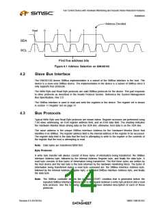
Address Decided
Start
0
1
0
1
1
SDA
SCL
First five address bits
Figure 4.1 Address Selection on EMC6D102
4.2
4.3
Slave Bus Interface
The EMC6D102 device SMBus implementation is a subset of the SMBus interface to the host. The
device is a slave-only SMBus device. The implementation in the device is a subset of SMBus since it
only supports four protocols.
The Write Byte and Read Byte protocols are valid SMBus protocols for the device. This part responds
to other protocols as described in the Invalid Protocol Section. Reference the System Management
Bus Specification, Rev 2.0.
The SMBus interface is used to read and write the registers in the device. The register set is shown
in section 11 Register Set on page 31.
Bus Protocols
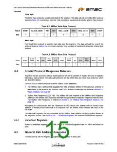
Typical Write Byte and Read Byte protocols are shown below. Register accesses are performed using
7-bit slave addressing, an 8-bit register address field, and an 8-bit data field. The shading indicates
the Hardware Monitor Block driving data on the SDA line; otherwise, host data is on the SDA line.
The slave address is the unique SMBus Interface Address for the Hardware Monitor Block that
identifies it on SMBus. The register address field is the internal address of the register to be accessed.
The register data field is the data that the host is attempting to write to the register or the contents of
the register that the host is attempting to read.
Note: Data bytes are transferred MSB first.
Byte Protocols
A write byte transfer will always consist of three bytes of information being transferred: the SMBus
Interface Address byte, followed by the Internal Address Register byte, and finally the data byte. A
read byte consists of four bytes of information being transferred. The first three bytes are written by
the host device and the last byte is the byte returned by the hardware monitoring block. The bytes of
information being transferred during a read byte command are: the SMBus Interface Address byte,
followed by the Internal Address Register byte, a repeated SMBus Interface Address byte, and finally
the data byte.
Note: The SMBus controller detects the repeated START condition that is generated before the
repeated SMBus Interface Address byte to distinguish between a write byte protocol and a read
byte protocol. See the following sections for a more detailed description of each of these
protocols.
Revision 0.4 (04-05-05)
SMSC EMC6D102
DATA1S4HEET

 SMSC [ SMSC CORPORATION ]