Fan Control Device with Hardware Monitoring and Acoustic Noise Reduction Features
Datasheet
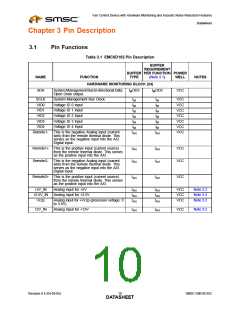
Chapter 3 Pin Description
3.1
Pin Functions
Table 3.1 EMC6D102 Pin Description
BUFFER
REQUIREMENT
BUFFER PER FUNCTION POWER
NAME
FUNCTION
TYPE
(Note 3.1)
WELL
NOTES
HARDWARE MONITORING BLOCK (24)
SDA
System Management Bus bi-directional Data.
IMOD3
IMOD3
VCC
Open Drain output.
System Management Bus Clock.
Voltage ID 0 Input
SCLK
VID0
VID1
VID2
VID3
IM
IM
IM
IM
IM
IM
IM
IM
IM
IM
VCC
VCC
VCC
VCC
VCC
VCC
VCC
Voltage ID 1 Input
Voltage ID 2 Input
Voltage ID 3 Input
Voltage ID 4 Input
This is the negative Analog input (current
sink) from the remote thermal diode. This
serves as the negative input into the A/D.
Digital Input.
VID4
Remote1-
IM
IAN
IM
IAN
Remote1+ This is the positive input (current source)
from the remote thermal diode. This serves
as the positive input into the A/D.
IAN
IAN
VCC
VCC
Remote2-
This is the negative Analog input (current
sink) from the remote thermal diode. This
serves as the negative input into the A/D.
Digital Input.
IAN
IAN
Remote2+ This is the positive input (current source)
from the remote thermal diode. This serves
as the positive input into the A/D.
IAN
IAN
VCC
+5V_IN
+2.5V_IN
Vccp
Analog input for +5V
Analog input for +2.5V
IAN
IAN
IAN
IAN
IAN
IAN
VCC
VCC
VCC
Note 3.2
Note 3.2
Note 3.2
Analog input for +Vccp (processor voltage: 0
to 3.0V).
12V_IN
Analog input for +12V
IAN
IAN
VCC
Note 3.2
Revision 0.4 (04-05-05)
SMSC EMC6D102
DATA1S0HEET

 SMSC [ SMSC CORPORATION ]