Fan Control Device with Hardware Monitoring and Acoustic Noise Reduction Features
Datasheet
4.6
Slave Device Time-Out
The EMC6D102 supports the slave device timeout as per the SMBus Specification, v2.0.
According to SMBus specification, v2.0 devices in a transfer can abort the transfer in progress and
release the bus when any single clock low interval exceeds 25ms (TTIMEOUT, MIN). Devices that have
detected this condition must reset their communication and be able to receive a new START condition
no later than 35ms (TTIMEOUT, MAX).
Note: Some simple devices do not contain a clock low drive circuit; this simple kind of device typically
may reset its communications port after a start or stop condition
4.7
Stretching the SCLK Signal
The EMC6D102 supports stretching of the SCLK by other devices on the SMBus. The Hardware
Monitor Block does not stretch the SCLK.
4.8
4.9
4.10
SMBus Timing
The SMBus Slave Interface complies with the SMBus AC Timing Specification. See the SMBus timing
diagram shown in the section titled Section 9.2, "SMBus Interface," on page 80.
Bus Reset Sequence
The SMBus Slave Interface will reset and return to the idle state upon a START field followed
immediately by a STOP field.
SMBus Alert Response Address
The EMC6D102 device responds to the SMBus Alert Response Address, 0001 100, if the INTEN bit
(register 7Ch bit 2) is set and one or more status events bits are high. The interrupt signal (INT#),
which can be enabled on either the PWM2 or TACH3 pins, can be used as the SMBALERT#. See the
section describing the Interrupt Status Registers on page 21 and the section describing the Interrupt
Pin on page 23 for more details on interrupts.
The device can signal the host that it wants to talk by pulling the SMBALERT# low, if a status bit is
set in one of the interrupt status registers and properly enabled onto the INT# pin. The host processes
the interrupt and simultaneously accesses all SMBALERT# devices through a modified Receive Byte
operation with the Alert Response Address (ARA).
The EMC6D102 device, which pulled SMBALERT# low, will acknowledge the Alert Response Address
and respond with its device address. The 7-bit device address provided by the EMC6D102 device is
placed in the 7 most significant bits of the byte. The eighth bit can be a zero or one.
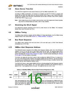
Table 4.4 Modified SMBus Receive Byte Protocol Response to ARA
ALERT
RESPONSE
ADDRESS
EMC6D102 SLAVE
ADDRESS
FIELD:
Bits:
START
RD
ACK
NACK
STOP
1
7
1
1
8
1
1
After acknowledging the slave address, the EMC6D102 device will disengage the SMBALERT# pull-
down by clearing the INT enable bit. If the condition that caused the interrupt remains, the Fan Control
device will reassert the SMBALERT# on the next monitoring cycle, provided the INT enable bit has
been set back to ‘1’ by software.
Revision 0.4 (04-05-05)
SMSC EMC6D102
DATA1S6HEET

 SMSC [ SMSC CORPORATION ]