Fan Control Device with Hardware Monitoring and Acoustic Noise Reduction Features
Datasheet
Chapter 5 Hardware Monitoring
The following sub-sections describe the EMC6D102 Hardware Monitoring features.
5.1
Input Monitoring
The EMC6D102 device’s monitoring function is started by writing a ‘1’ to the START bit in the
Ready/Lock/Start Register (0x40). Measured values from the analog inputs and temperature sensors
are stored in Reading Registers. The values in the reading registers can be accessed via the SMBus
interface. These values are compared to the programmed limits in the Limit Register. The out-of-limit
and diode fault conditions are stored in the Interrupt Status Registers.
5.2
Resetting the EMC6D102
5.2.1
Power-On Reset
All the registers in the Hardware Monitor Block, except the reading registers, reset to a default value
when power is applied to the block. The default state of the register is shown in the table in the
Register Summary subsection. The default state of Reading Registers are not shown because these
registers have indeterminate power on values.
Note: Usually the first action after power up is to write limits into the Limit Registers.
5.2.2
Soft Reset (Initialization)
Setting bit 7 of the CONF register performs a soft reset. This bit is self-clearing. Soft Reset performs
reset on all the registers except the Reading Registers.
5.3
Monitoring Modes
The Hardware Monitor Block supports two Monitoring modes: Continuous Mode and Cycle Mode.
These modes are selected using bit 1 of the Special Function Register (7Ch). The following
subsections contain a description of these monitoring modes.
The hardware monitor conversion clock is 45KHz ± 10%. Temperature conversions take 96 clocks,
each (2.133ms nom.); voltage conversions take 68 clocks, each (1.511ms nom). The time to complete
a conversion cycle depends upon the number of inputs in the conversion sequence to be measured
(see Table 5.3, “ADC Conversion Sequence,” on page 20) and the amount of averaging per input,
which is selected using the AVG[2:0] bits in the Special Function register (see on page 68).
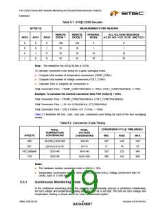
For each mode, there are four options for the number of measurements that are averaged for each
temperature and voltage reading. These options are selected using bits[7:5] of the Special Function
register (7Ch). These bits are defined as follows:
Bits [7:5] AVG[2:0]
The AVG[2:0] bits determine the amount of averaging for each of the measurements that are performed
by the hardware monitor before the reading registers are updated (Table 5.1). The AVG[2:0] bits are
priority encoded where the most significant bit has highest priority. For example, when the AVG2 bit
is asserted, 32 averages will be performed for each measurement before the reading registers are
updated regardless of the state of the AVG[1:0] bits.
Revision 0.4 (04-05-05)
SMSC EMC6D102
DATA1S8HEET

 SMSC [ SMSC CORPORATION ]