Legacy-Free Keyboard/Embedded Controller with SPI and LPC Docking Interface
5.3
FIFO Polled Mode Operation
With FCR bit 0 = "1", resetting IER bits 0, 1, 2 or 3 or all to zero puts the UART in the FIFO Polled
Mode of operation. Since the RCVR and XMITTER are controlled separately, either one or both can be
in the polled mode of operation.
In this mode, the user's program will check RCVR and XMITTER status via the LSR. LSR definitions
for the FIFO Polled Mode are as follows:
Bit 0 = ‘1’ as long as there is one byte in the RCVR FIFO.
Bits 1:4 specify which error(s) have occurred. Character error status is handled the same way as when
in the interrupt mode, the IIR is not affected since EIR bit 2=0.
Bit 5 indicates when the XMIT FIFO is empty.
Bit 6 indicates that both the XMIT FIFO and shift register are empty.
Bit 7 indicates whether there are any errors in the RCVR FIFO.
There is no trigger level reached or timeout condition indicated in the FIFO Polled Mode, however, the
RCVR and XMIT FIFOs are still fully capable of holding characters.
5.3.1
Effect of the Reset on the Register File
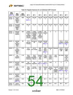
The Reset Function Table (Table 5.7) details the effect of Vcc2 POR or nRESET_OUT on each of the
registers of the Serial Port.
Table 5.7 Reset Function Table
REGISTER/SIGNAL
RESET CONTROL
RESET STATE
Interrupt Enable Register
Interrupt Identification Reg.
FIFO Control
RESET
All bits low
Bit 0 is high; Bits 1 - 7 low
All bits low
Line Control Reg.
MODEM Control Reg.
Line Status Reg.
MODEM Status Reg.
TXD1, TXD2
All bits low except 5, 6 high
All bits low
High
INTRPT (RCVR errs)
INTRPT (RCVR Data Ready)
INTRPT (THRE)
OUT2B
RESET/Read LSR
RESET/Read RBR
RESET/Read IIR/Write THR
RESET
Low
High
RTSB
DTRB
OUT1B
RESET
High
RCVR FIFO
RESET/ FCR1*FCR0/_FCR0
All Bits Low
XMIT FIFO
SMSC LPC47N350
Revision 1.1 (01-14-03)
DATA3S5HEET

 SMSC [ SMSC CORPORATION ]