ST7565S
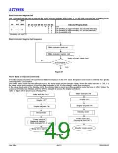
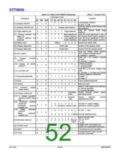
COMMAND DESCRIPTION
Instruction Setup: Reference
(1) Initialization
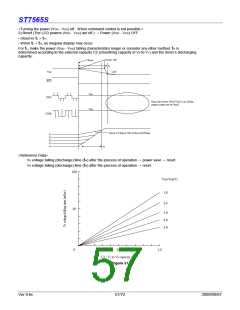
Note: With this IC, when the power is applied, LCD driving non-selective potentials V2 and V3 (SEG pin) and V1 and V4 (COM pin)
are output through the LCD driving output pins SEG and COM. When electric charge is remaining in the smoothing capacitor
connecting between the LCD driving voltage output pins (V ~ V ) and the VDD pin, the picture on the display may become totally
1
5
dark instantaneously when the power is turned on. To avoid occurrence of such a failure, we recommend the
following flow when turning on the power.
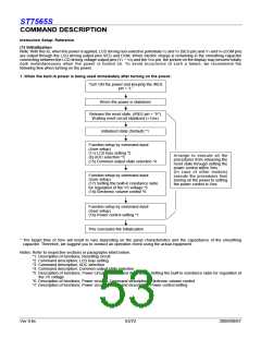
1. When the built-in power is being used immediately after turning on the power:
Turn ON the power and keeping the /RES
pin = “L”
When the power is stabilized
Release the reset state. (/RES pin = “H”)
Waiting reset circuit stabilized (<1ms)
Initialized state (Default) *1
Function setup by command input
(User setup)
(11) LCD bias setting *2
(8) ADC selection *3
(15) Common output state selection *4
Arrange to execute all the
procedures from releasing the
reset state through setting the
power control within 5ms.
(In case of other models)
Function setup by command input
(User setup)
(17) Setting the built-in resistance radio
for regulation of the V5 voltage *5
(18) Electronic volume control *6
execute the procedures from
turning on the power to setting
the power control in 5ms.
Function setup by command input
(User setup)
(16) Power control setting *7
This concludes the initialization
* The target time of 5ms will result to vary depending on the panel characteristics and the capacitance of the smoothing
capacitor. Therefore, we suggest you to conduct an operation check using the actual equipment.
Notes: Refer to respective sections or paragraphs listed below.
*1: Description of functions; Resetting circuit
*2: Command description; LCD bias setting
*3: Command description; ADC selection
*4: Command description; Common output state selection
*5: Description of functions; Power circuit & Command description; Setting the built-in resistance radio for regulation of
the V5 voltage
*6: Description of functions; Power circuit & Command description; Electronic volume control
*7: Description of functions; Power circuit & Command description; Power control setting
Ver 0.6c
53/72
2009/09/07

 SITRONIX [ SITRONIX TECHNOLOGY CO., LTD. ]